Nissan Juke Service and Repair Manual : P0826 up and down shift SW
DTC Logic
DTC DETECTION LOGIC
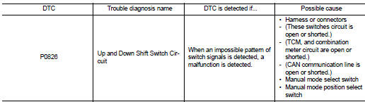
DTC CONFIRMATION PROCEDURE
CAUTION:
Always drive vehicle at a safe speed.
NOTE:
If “DTC CONFIRMATION PROCEDURE” has been previously conducted, always turn ignition switch OFF and wait at least 10 seconds before conducting the next test.
After the repair, perform the following procedure to confirm the malfunction is eliminated.
1.CHECK DTC DETECTION
 With CONSULT-III
1. Turn ignition switch ON.
2. Select “DATA MONITOR” in “TRANSMISSION”.
3. Start engine.
4. Drive vehicle for at least 2 consecutive seconds.
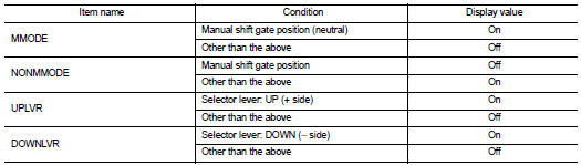
MMODE : ON
Is “P0826” detected? YES >> Go to TM-227, "Diagnosis Procedure".
NO >> Check intermittent incident. Refer to GI-42, "Intermittent Incident".
Diagnosis Procedure
1.CHECK MANUAL MODE SWITCH CIRCUIT
 With CONSULT-III
1. Turn ignition switch ON.
2. Select “DATA MONITOR”.
3. Check the ON/OFF operations of each monitor item.
Without CONSULT-III
Drive the vehicle in the manual mode and shift lever to the “UP (+ side)” or “(− side)” side (1st ⇔ 6th gear).Check that the meter indicator coincides with the actual gear position.
Is the inspection result normal? YES >> GO TO 5.
NO >> GO TO 2.
2.CHECK MANUAL MODE SWITCH
Check manual mode switch. Refer to TM-228, "Component Inspection".
Is the inspection result normal? YES >> GO TO 3.
NO >> Repair or replace damaged parts.
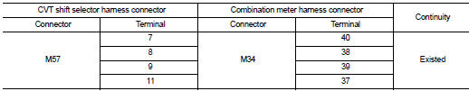
3.CHECK HARNESS BETWEEN CVT SHIFT SELECTOR HARNESS CONNECTOR AND COMBINATION METER HARNESS CONNECTOR
1. Turn ignition switch OFF.
2. Disconnect CVT shift selector harness connector and combination meter harness connector.
3. Check continuity between CVT shift selector harness connector terminals and combination meter harness connector terminals.
4. If OK, check harness for short to ground and short to power.
Is the inspection result normal? YES >> GO TO 4.
NO >> Repair or replace damaged parts.
4.CHECK GROUND CIRCUIT
1. Check continuity between CVT shift selector harness connector terminals and ground.

2. If OK, check harness for short to ground and short to power.
3. Reinstall any part removed.
Is the inspection result normal? YES >> GO TO 5.
NO >> Repair or replace damaged parts.
5.CHECK TCM
Check TCM input/output signals. Refer to TM-164, "Reference Value".
Is the inspection result normal? YES >> Check intermittent incident. Refer to GI-42, "Intermittent Incident".
NO >> Replace the TCM. Refer to TM-280, "Removal and Installation".
Component Inspection
MANUAL MODE SWITCH
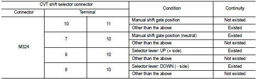
1.MANUAL MODE SWITCH
Check continuity between CVT shift selector connector terminals.
Is the inspection result normal? YES >> INSPECTION END
NO >> Repair or replace damaged parts.
 P0778 pressure control solenoid B
DTC Logic
DTC DETECTION LOGIC
DTC CONFIRMATION PROCEDURE
NOTE:
If “DTC CONFIRMATION PROCEDURE” has been previously performed, always turn
ignition switch
OFF and wait at least 10 seconds befo ...
 P0840 transmission fluid pressure SEN/SW A
DTC Logic
DTC DETECTION LOGIC
DTC CONFIRMATION PROCEDURE
NOTE:
If “DTC CONFIRMATION PROCEDURE” has been previously performed, always turn
ignition switch
OFF and wait at least 10 seconds befo ...
Other materials:
Final drive
Exploded View
1. Differential side bearing outer race
2. Differential side bearing
3. Final drive
: Replace the parts as a set.
Disassembly
1. Remove differential side bearings, using the drift (A) [SST:
ST33052000] and a puller [Commercial service tool].
Assembly
1. Install different ...
U1010 control unit (can)
Description
Initial diagnosis of A/C auto amp.
DTC Logic
DTC DETECTION LOGIC
DTC CONFIRMATION PROCEDURE
1.PERFORM SELF-DIAGNOSIS
With CONSULT-III
1. Turn ignition switch ON.
2. Select “Self Diagnostic Result” mode of “PTC HEATER” using CONSULT-.III
3. Check DTC.
Is DTC detected?
YES & ...
P2263 TC system
DTC Logic
DTC DETECTION LOGIC
Diagnosis Procedure
1.CHECK VACUUM HOSES AND VACUUM GALLERY
1. Turn ignition switch OFF.
2. Check vacuum hoses and vacuum gallery for clogging, cracks
or improper connection. Refer to EC-825, "TURBOCHARGER
BOOST CONTROL : Vacuum Hose Drawing".
Is t ...
