Nissan Juke Service and Repair Manual : P0720 output speed sensor
DTC Logic
DTC DETECTION LOGIC
DTC CONFIRMATION PROCEDURE
CAUTION:
Be careful of the driving speed.
1.PREPARATION BEFORE WORK
If another "DTC CONFIRMATION PROCEDURE" occurs just before, turn ignition switch OFF and wait for at least 10 seconds, then perform the next test.
>> GO TO 2.
2.CHECK DTC DETECTION
1. Start the engine.
2. Drive the vehicle.
3. Maintain the following conditions for 10 seconds or more.
Selector lever : “D” position Vehicle speed : 55 km/h (34 MPH) or more
4. Stop the vehicle.
5. Check the first trip DTC.
Is “P0720” detected? YES >> Go to TM-413, "Diagnosis Procedure".
NO >> INSPECTION END
Diagnosis Procedure
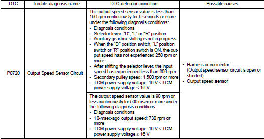
1.CHECK OUTPUT SPEED SENSOR POWER CIRCUIT
Check the voltage between the output speed sensor harness connector terminal and ground.
Is the check result normal? YES >> GO TO 6.
NO >> GO TO 2.
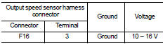
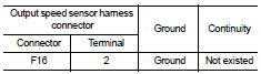
2.CHECK OUTPUT SPEED SENSOR GROUND CIRCUIT
Check the continuity between the output speed sensor harness connector terminal and ground.
Is the check result normal? YES >> GO TO 3.
NO >> Repair or replace the malfunctioning parts.
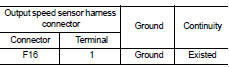
3.CHECK CIRCUIT BETWEEN OUTPUT SPEED SENSOR AND TCM (PART 1)
1. Turn ignition switch OFF.
2. Disconnect the TCM connector.
3. Check the continuity between the output speed sensor harness connector terminal and the TCM harness connector terminal.
Is the check result normal? YES >> GO TO 4.
NO >> Repair or replace the malfunctioning parts.
4.CHECK CIRCUIT BETWEEN OUTPUT SPEED SENSOR AND TCM (PART 1)
Check the continuity between the output speed sensor harness connector terminal and ground.
Is the check result normal? YES >> GO TO 5.
NO >> Repair or replace the malfunctioning parts.
5.CHECK TCM INPUT SIGNALS
1. Connect all of the disconnected connectors.
2. Lift the vehicle.
3. Start the engine.
4. Check the frequency of the output speed sensor.
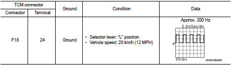
Is the check result normal? YES >> Check intermittent incident. Refer to GI-42, "Intermittent Incident".
NO >> Replace the output speed sensor. Refer to TM-497, "Exploded View".
6.CHECK CIRCUIT BETWEEN IPDM E/R AND OUTPUT SPEED SENSOR (PART 1)
1. Disconnect the IPDM E/R connector.
2. Check the continuity between the IPDM E/R harness connector terminal and the output speed sensor harness connector terminal.
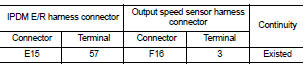
Is the check result normal? YES >> GO TO 7.
NO >> Repair or replace the malfunctioning parts.
7.CHECK CIRCUIT BETWEEN IPDM E/R AND OUTPUT SPEED SENSOR (PART 2)
Check the continuity between the IPDM E/R vehicle-side harness connector terminal and ground.
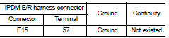
Is the check result normal? YES >> GO TO 8.
NO >> Repair or replace the malfunctioning parts.
8.DETECTION OF MALFUNCTION ITEMS
Check the following items: • Harness open circuit or short circuit between the ignition switch and IPDM E/R. Refer to PG-15, "Wiring Diagram - IGNITION POWER SUPPLY -".
• 10A fuse (No.55, IPDM E/R). Refer to PG-25, "Fuse, Connector and Terminal Arrangement".
• IPDM E/R
Is the check result normal? YES >> Check intermittent incident. Refer to GI-42, "Intermittent Incident".
NO >> Repair or replace the malfunctioning parts.
 P0715 input speed sensor A
DTC Logic
DTC DETECTION LOGIC
DTC CONFIRMATION PROCEDURE
CAUTION:
Be careful of the driving speed.
1.PREPARATION BEFORE WORK
If another "DTC CONFIRMATION PROCEDURE" occurs just befor ...
 P0740 torque converter
DTC Logic
DTC DETECTION LOGIC
DTC CONFIRMATION PROCEDURE
CAUTION:
Be careful of the driving speed.
1.PREPARATION BEFORE OPERATION (PART 1)
If another "DTC CONFIRMATION PROCEDURE" occ ...
Other materials:
B2581, B2582 intake sensor
DTC Logic
DTC DETECTION LOGIC
NOTE:
• If DTC is displayed along with DTC U1000, first perform the trouble diagnosis
for DTC U1000. Refer to HAC-
51, "DTC Logic".
• If DTC is displayed along with DTC U1010, first perform the trouble diagnosis
for DTC U1010. HAC-52,
"DTC Logic ...
Super lock actuator
Driver side : Component Function Check
1.CHECK FUNCTION
1. Select “DOOR LOCK” of “BCM” using CONSULT-III.
2. Select “SUPER LOCK” in “ACTIVE TEST” mode.
3. Check that the function operates normally according to the following
conditions.
Is the inspection result normal?
YES >> Super lo ...
System description
VENTILATION SYSTEM
System Description
OUTLINE
Ventilation system is controlled by A/C auto amp. (AUTOMATIC AIR
CONDITIONING) or A/C control (MANUAL
AIR CONDITIONING and MANUAL HEATER). For details of air conditioner system,
refer to HAC-17,
"System Description" (AUTOMATIC AIR COND ...
