Nissan Juke Service and Repair Manual : P0720 output speed sensor
DTC Logic
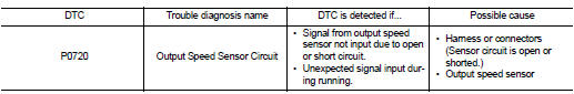
DTC DETECTION LOGIC
DTC CONFIRMATION PROCEDURE
CAUTION:
Always drive vehicle at a safe speed.
NOTE:
If “DTC CONFIRMATION PROCEDURE” has been previously performed, always turn ignition switch OFF and wait at least 10 seconds before performing the next test.
After the repair, perform the following procedure to confirm the malfunction is eliminated.
1.CHECK DTC DETECTION
 With CONSULT-III
1. Turn ignition switch ON.
2. Select “DATA MONITOR”.
3. Start engine and maintain the following conditions for at least 12 consecutive seconds.
ACC PEDAL OPEN : More than 1.0/8
RANGE : “D” position
Driving location : Driving the vehicle uphill (increased
engine load) will help
maintain the driving conditions
required for this test.
4. If DTC is detected,
 With GST
Follow the procedure “With CONSULT-III”.
Is “P0720” detected? YES >> Go to TM-209, "Diagnosis Procedure".
NO >> Check intermittent incident. Refer to GI-42, "Intermittent Incident".
Diagnosis Procedure
1. CHECK POWER AND SENSOR GROUND
1. Turn ignition switch OFF.
2. Disconnect the secondary speed sensor harness connector.
3. Turn ignition switch ON.
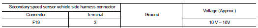
4. Check voltage between secondary speed sensor harness connector terminals.
Is the inspection result normal? YES >> GO TO 2.
NO >> GO TO 5.
2. CHECK TCM INPUT SIGNAL
1. Turn ignition switch OFF.
2. Connect the secondary speed sensor harness connector.
3. Start engine.
4. Lift up the vehicle.
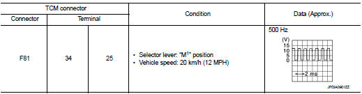
5. Check frequency of secondary speed sensor.
Is the inspection result normal? YES >> GO TO 8.
NO >> GO TO 3.
3. CHECK HARNESS BETWEEN TCM AND SECONDARY SPEED SENSOR (PART 1)
1. Turn ignition switch OFF.
2. Disconnect TCM connector and secondary speed sensor harness connector.
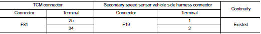
3. Check continuity between TCM connector terminal and secondary speed sensor harness connector terminal.
Is the inspection result normal? YES >> GO TO 4.
NO >> Repair or replace damaged parts.
4. CHECK HARNESS BETWEEN TCM AND SECONDARY SPEED SENSOR (PART 2)
Check continuity between TCM connector terminal and ground.
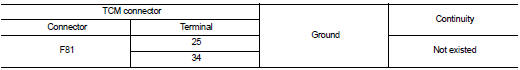
Is the inspection result normal? YES >> GO TO 5.
NO >> Repair or replace damaged parts.
5. CHECK CVT UNIT CIRCUIT
1. Disconnect CVT unit connector.
2. Check continuity between CVT unit connector terminals and ground.
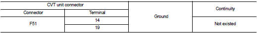
Is the inspection result normal? YES >> GO TO 6.
NO >> Repair or replace damaged parts.
6. CHECK HARNESS BETWEEN SECONDARY SPEED SENSOR (POWER) AND IPDM E/R (PART 1)
1. Turn ignition switch OFF.
2. Disconnect IPDM E/R connector.
3. Check continuity between secondary speed sensor vehicle side harness connector terminal and IPDM E/ R vehicle side harness connector terminal.
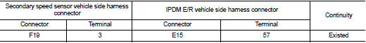
Is the inspection result normal? YES >> GO TO 7.
NO >> Repair or replace damaged parts.
7. CHECK HARNESS BETWEEN SECONDARY SPEED SENSOR (POWER) AND IPDM E/R (PART 1)
Check continuity between secondary speed sensor vehicle side harness connector terminal and ground.
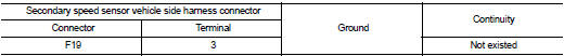
Is the inspection result normal? YES >> GO TO 8.
NO >> Repair or replace damaged parts.
8.DETECT MALFUNCTIONING ITEMS
Check the following. Refer to PG-15, "Wiring Diagram - IGNITION POWER SUPPLY -".
• IPDM E/R
• 10A fuse (No.55, located in the IPDM E/R)
• Harness for short or open between IPDM E/R and ignition switch
• Ignition switch
Is the inspection result normal? YES >> Check intermittent incident. Refer to GI-42, "Intermittent Incident" NO >> Repair or replace damaged parts.
9.CHECK INTERMITTENT INCIDENT
Refer to GI-42, "Intermittent Incident".
Is the inspection result normal? YES >> Replace secondary speed sensor. Refer to TM-291, "Removal and Installation".
NO >> Repair or replace damaged parts.
 P0717 input speed sensor A
DTC Logic
DTC DETECTION LOGIC
DTC CONFIRMATION PROCEDURE
CAUTION:
Always drive vehicle at a safe speed.
NOTE:
If “DTC CONFIRMATION PROCEDURE” has been previously performed, always turn
ignit ...
 P0725 engine speed
Description
The engine speed signal is transmitted from ECM to TCM by CAN communication
line.
DTC Logic
DTC DETECTION LOGI
DTC CONFIRMATION PROCEDURE
CAUTION:
Always drive vehicle at a safe ...
Other materials:
SRS air bag warning lamp does not turn off
Diagnosis Procedure
1.CHECK AIR BAG MODULE AND SEAT BELT PRE-TENSIONER
Check the deployment of air bag module.
Is air bag module deployed?
YES >> Replace the malfunctioning parts.
NO >> GO TO 2.
2.CHECK AIR BAG FUSE
Check 10 A fuse [No.2, located in fuse block (J/B)].
Is ...
Traction AA, A, B and C
The traction grades, from highest to lowest, are AA, A, B and C. Those grades
represent the tire’s ability to stop on wet pavement as measured under controlled
conditions on specified government test surfaces of asphalt and concrete. A tire
marked C may have poor traction performance.
WARNING ...
FM-AM-SAT radio with Compact Disc (CD) player (Type B)
1. XM band select button
2. CD insert slot
3. CD EJECT button
4. TUNE/SCROLL knob and AUDIO control button
5. Radio station preset buttons
6. AUX button
7. ON·OFF button/VOLUME control knob
8. FF (forward)/REW (rewind) or SEEK/CATEGORY button
9. CD button
10. FM·AM band select button
No ...
