Nissan Juke Service and Repair Manual : P0706 transmission range sensor A
DTC Logic
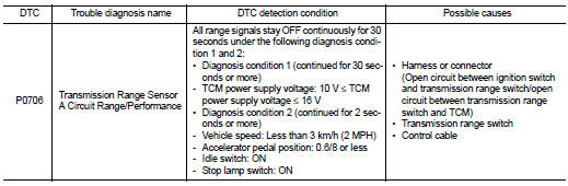
DTC DETECTION LOGIC
DTC CONFIRMATION PROCEDURE
1.PREPARATION BEFORE WORK
If another "DTC CONFIRMATION PROCEDURE" occurs just before, turn ignition switch OFF and wait for at least 10 seconds, then perform the next test.
>> GO TO 2.
2.PERFORM DTC CONFIRMATION PROCEDURE
1. Start the engine.
2. Maintain the following conditions.
Accelerator pedal position : 0.0/8
Brake pedal : Depressed
Vehicle speed : 0 km/h (0 MPH)
3. Shift the selector lever through entire positions from “P” to “L”. (Hold
the selector lever at each position for
35 seconds or more.)
4. Check the first trip DTC.
Is “P0706” detected? YES >> Go to TM-400, "Diagnosis Procedure".
NO >> INSPECTION END
Diagnosis Procedure
1.ADJUSTMENT OF CONTROL CABLE
Adjust the control cable. Refer to TM-383, "Inspection and Adjustment".
>> GO TO 2.
2.PERFORM DTC CONFIRMATION PROCEDURE
 With CONSULT-III
1. Turn ignition switch ON.
2. Select “Self Diagnostic Results” in “TRANSMISSION”.
3. Touch “Erase”.
4. Perform "DTC CONFIRMATION PROCEDURE". Refer to TM-400, "DTC Logic".
Is “P0706” detected? YES >> GO TO 3.
NO >> INSPECTION END
3.CHECK POWER CIRCUIT
1. Turn the ignition switch OFF.
2. Disconnect the transmission range switch connector.
3. Turn ignition switch ON.
4. Check the voltage between the transmission range switch harness connector and body ground.
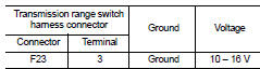
Is the check result normal? YES >> GO TO 4.
NO >> GO TO 7.
4.CHECK CIRCUIT BETWEEN TRANSMISSION RANGE SWITCH AND TCM (PART 1)
1. Turn the ignition switch OFF.
2. Disconnect the TCM connector.
3. Check the continuity between the transmission range switch harness connector and the TCM harness connector.
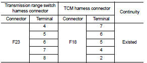
Is the check result normal? YES >> GO TO 5.
NO >> Repair or replace the malfunctioning parts.
5.CHECK CIRCUIT BETWEEN TRANSMISSION RANGE SWITCH AND TCM (PART 2)
Check the continuity between the transmission range switch harness connector and the TCM harness connector.
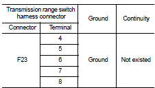
Is the check result normal? YES >> GO TO 6.
NO >> Repair or replace the malfunctioning parts.
6.CHECK TRANSMISSION RANGE SWITCH
Check the transmission range switch. Refer to TM-402, "Component Inspection (Transmission Range Switch)".
Is the check result normal? YES >> Check intermittent incident. Refer to GI-42, "Intermittent Incident".
NO >> Repair or replace the malfunctioning parts.
7.CHECK CIRCUIT BETWEEN IPDM E/R AND TRANSMISSION RANGE SWITCH (PART 1)
1. Disconnect the IPDM E/R connector.
2. Check the continuity between the IPDM E/R vehicle-side harness connector and the transmission range switch.
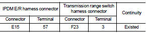
Is the check result normal? YES >> GO TO 8.
NO >> Repair or replace the malfunctioning parts.
8.CHECK CIRCUIT BETWEEN IPDM E/R AND TRANSMISSION RANGE SWITCH (PART 2)
Check the continuity between the IPDM E/R vehicle-side harness connector and the transmission range switch.
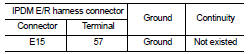
Is the check result normal? YES >> GO TO 9.
NO >> Repair or replace the malfunctioning parts.
9.DETECTION OF MALFUNCTION ITEMS
Check the following items: • Harness open circuit or short circuit between the ignition switch and IPDM E/R. Refer to PG-15, "Wiring Diagram - IGNITION POWER SUPPLY -".
• 10A fuse (No. 55, IPDM E/R). Refer to PG-25, "Fuse, Connector and Terminal Arrangement".
• IPDM E/R Is the check result normal? YES >> Check intermittent incident. Refer to GI-42, "Intermittent Incident".
NO >> Repair or replace the malfunctioning parts.
Component Inspection (Transmission Range Switch)
1.CHECK TRANSMISSION RANGE SWITCH
Check the continuity between the transmission range switch connector terminals.
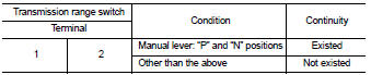
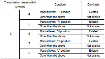
Is the inspection result normal? YES >> INSPECTION END
NO >> There is a malfunction of the transmission range switch. Replace the transaxle assembly. Refer to TM-508, "Removal and Installation".
 P0705 transmission range switch A
DTC Logic
DTC DETECTION LOGIC
DTC CONFIRMATION PROCEDURE
CAUTION:
Be careful of the driving speed.
1.PREPARATION BEFORE WORK
If another "DTC CONFIRMATION PROCEDURE" occurs just befor ...
 P0711 transmission fluid temperature sensor A
DTC Logic
DTC DETECTION LOGIC
DTC CONFIRMATION PROCEDURE
1.PREPARATION BEFORE WORK
If another "DTC CONFIRMATION PROCEDURE" occurs just before, turn ignition
switch OFF and wait for a ...
Other materials:
P0011 IVT control
DTC Logic
DTC DETECTION LOGIC
NOTE:
If DTC P0011 is displayed with DTC P0075, first perform the trouble diagnosis
for DTC P0075. Refer to
EC-583, "DTC Logic".
DTC CONFIRMATION PROCEDURE
1.PRECONDITIONING
If DTC Confirmation Procedure has been previously conducted, always turn
...
Wiring diagram
SRS AIR BAG SYSTEM
Wiring Diagram
For connector terminal arrangements, harness layouts, and alphabets in a
(option abbreviation; if not
described in wiring diagram), refer to GI-12, "Connector Information/Explanation
of Option Abbreviation".
...
Precaution for Supplemental Restraint System (SRS) "AIR BAG" and "SEAT BELT
PRE-TENSIONER"
The Supplemental Restraint System such as “AIR BAG” and “SEAT BELT PRE-TENSIONER”,
used along
with a front seat belt, helps to reduce the risk or severity of injury to the
driver and front passenger for certain
types of collision. Information necessary to service the system safely is
include ...
