Nissan Juke Service and Repair Manual : P0705 transmission range switch A
DTC Logic
DTC DETECTION LOGIC
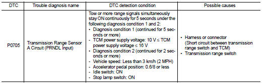
DTC CONFIRMATION PROCEDURE
CAUTION:
Be careful of the driving speed
.
1.PREPARATION BEFORE WORK
If another "DTC CONFIRMATION PROCEDURE" occurs just before, turn ignition switch OFF and wait for at least 10 seconds, then perform the next test.
>> GO TO 2.
2.CHECK DTC DETECTION
1. Start the engine.
2. Maintain the following conditions.
Accelerator pedal position : 0.0/8
Brake pedal : Depressed
Vehicle speed : 0 km/h (0 MPH)
3. Shift the selector lever through entire positions from “P” to “L”. (Hold
the selector lever at each position for
10 seconds or more.)
4. Check the first trip DTC.
Is “P0705” detected? YES >> Go to TM-394, "Diagnosis Procedure".
NO >> INSPECTION END
Diagnosis Procedure
1.CHECK TCM INPUT SIGNALS
 With CONSULT-III
1. Turn ignition switch ON.
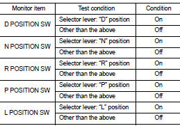
2. Select “Data Monitor” in “TRANSMISSION”.
3. Select “D POSITION SW”, “N POSITION SW”, “R POSITION SW”, “P POSITION SW” and “L POSITION SW”.
4. Shift the selector lever through entire positions from “P” to “L” and check ON/OFF of each monitor item.
 Without CONSULT-III.
1. Turn the ignition switch OFF.
2. Disconnect the TCM connector.
3. Turn ignition switch ON.
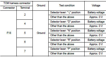
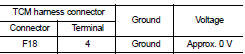
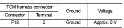
4. Shift the selector lever from “P” to “L” and check the voltage between the TCM harness connector terminal and the ground.
Is the check result normal? YES >> Check intermittent incident. Refer to GI-42, "Intermittent Incident".
NO-1 [“D POSITION SW” is “ON” when selector is not in “D” position. (Or connector terminal 4 is at power voltage.)]>>GO TO 2.
NO-2 [“N POSITION SW” is “ON” when selector is not in “N” position. (Or connector terminal 5 is at power voltage.)]>>GO TO 4.
NO-3 [“R POSITION SW” is “ON” when selector is not in “R” position. (Or connector terminal 6 is at power voltage.)]>>GO TO 6.
NO-4 [“P POSITION SW” is “ON” when selector is not in “P” position. (Or connector terminal 7 is at power voltage.)]>>GO TO 8.
NO-5 [“L POSITION SW” is “ON” when selector is not in “L” position. (Or connector terminal 2 is at power voltage.)]>>GO TO 10.
2.CHECK D POSITION SW CIRCUIT (PART 1)
1. Turn the ignition switch OFF.
2. Disconnect the TCM connector.
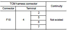
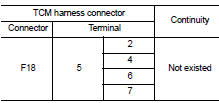
3. Check the continuity between the TCM harness connector terminals.
Is the check result normal? YES >> GO TO 3.
NO >> Repair or replace the malfunctioning parts.
3.CHECK D POSITION SW CIRCUIT (PART 2)
1. Disconnect the transmission position switch connector.
2. Turn ignition switch ON.
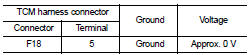
3. Check the voltage between the TCM harness connector and ground.
Is the check result normal? YES >> GO TO 12.
NO >> Repair or replace the malfunctioning parts.
4.CHECK N POSITION SW CIRCUIT (PART 1)
1. Turn the ignition switch OFF.
2. Disconnect the TCM connector.
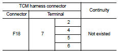
3. Check the continuity between the TCM harness connector terminals.
Is the check result normal? YES >> GO TO 5.
NO >> Repair or replace the malfunctioning parts.
5.CHECK N POSITION SW CIRCUIT (PART 2)
1. Disconnect the transmission position switch connector.
2. Turn ignition switch ON.
3. Check the voltage between the TCM harness connector and ground.
Is the check result normal? YES >> GO TO 12.
NO >> Repair or replace the malfunctioning parts.
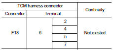
6.CHECK P POSITION SW CIRCUIT (PART 1)
1. Turn the ignition switch OFF.
2. Disconnect the TCM connector.
3. Check the continuity between the TCM harness connector terminals.
Is the check result normal? YES >> GO TO 7.
NO >> Repair or replace the malfunctioning parts.
7.CHECK P POSITION SW CIRCUIT (PART 2)
1. Disconnect the transmission position switch connector.
2. Turn ignition switch ON.
3. Check the voltage between the TCM harness connector and ground.
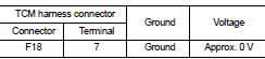
Is the check result normal? YES >> GO TO 12.
NO >> Repair or replace the malfunctioning parts.
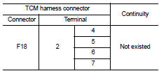
8.CHECK R POSITION SW CIRCUIT (PART1)
1. Turn the ignition switch OFF.
2. Disconnect the TCM connector.
3. Check the continuity between the TCM harness connector terminals
Is the check result normal? YES >> GO TO 9.
NO >> Repair or replace the malfunctioning parts.
9.CHECK R POSITION SW CIRCUIT (PART 2)
1. Disconnect the transmission position switch connector.
2. Turn ignition switch ON.
3. Check the voltage between the TCM harness connector and ground.
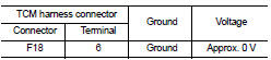
Is the check result normal? YES >> GO TO 12.
NO >> Repair or replace the malfunctioning parts.
10.CHECK 1: L POSITION SWITCH CIRCUIT (PART 1)
1. Turn the ignition switch OFF.
2. Disconnect the TCM connector.
3. Check the continuity between the TCM harness connector terminals.
Is the check result normal? YES >> GO TO 11.
NO >> Repair or replace the malfunctioning parts.
11.CHECK 2: L POSITION SWITCH CIRCUIT (PART 2)
1. Disconnect the transmission position switch connector.
2. Turn ignition switch ON.
3. Check the voltage between the TCM harness connector and ground.
Is the check result normal? YES >> GO TO 12.
NO >> Repair or replace the malfunctioning parts.
12.CHECK TRANSMISSION RANGE SWITCH
Check the transmission range switch. Refer to TM-398, "Component Inspection (Transmission Range Switch)".
Is the check result normal? YES >> Check intermittent incident. Refer to GI-42, "Intermittent Incident".
NO >> Repair or replace the malfunctioning parts.
Component Inspection (Transmission Range Switch)
1.CHECK TRANSMISSION RANGE SWITCH
Check the continuity between the transmission range switch connector terminals.
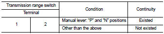
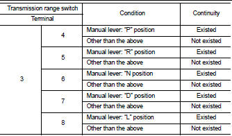
Is the inspection result normal? YES >> INSPECTION END
NO >> There is a malfunction of the transmission range switch. Replace the transaxle assembly. Refer to TM-508, "Removal and Installation".
 P062f eeprom
DTC Logic
DTC DETECTION LOGIC
DTC CONFIRMATION PROCEDURE
1.PREPARATION BEFORE WORK
If another "DTC CONFIRMATION PROCEDURE" occurs just before, turn ignition
switch OFF and wait for a ...
 P0706 transmission range sensor A
DTC Logic
DTC DETECTION LOGIC
DTC CONFIRMATION PROCEDURE
1.PREPARATION BEFORE WORK
If another "DTC CONFIRMATION PROCEDURE" occurs just before, turn ignition
switch OFF and wait for a ...
Other materials:
Door does not lock/unlock with door key cylinder operation
Diagnosis Procedure
1.CHECK POWER DOOR LOCK OPERATION
Check power door lock operation.
Does door lock/unlock with door lock and unlock switch?
YES >> GO TO 2.
NO >> Go to DLK-415, "ALL DOOR : Diagnosis Procedure".
2.CHECK UNLOCK SENSOR
Check unlock sensor.
Refer ...
Precaution
Precaution for Supplemental Restraint System (SRS) "AIR BAG" and "SEAT
BELT
PRE-TENSIONER"
The Supplemental Restraint System such as “AIR BAG” and “SEAT BELT
PRE-TENSIONER”, used along
with a front seat belt, helps to reduce the risk or severity of injury to the
driver a ...
Magnet clutch
Component Function Check
1.CHECK MAGNET CLUTCH OPERATION
Perform auto active test of IPDM E/R. Refer to PCS-12, "Diagnosis
Description" (with Intelligent Key) or PCS-
43, "Diagnosis Description" (without Intelligent Key).
Does it operate normally?
YES >> INSPECTION ...
