Nissan Juke Service and Repair Manual : P0705 transmission range switch A
DTC Logic
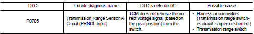
DTC DETECTION LOGIC
DTC CONFIRMATION PROCEDURE
CAUTION:
Always drive vehicle at a safe speed.
NOTE
:
If “DTC CONFIRMATION PROCEDURE” has been previously performed, always turn
ignition switch
OFF and wait at least 10 seconds before performing the next test.
After the repair, perform the following procedure to confirm the malfunction is eliminated.
1.CHECK DTC DETECTION
 With CONSULT-III
1. Turn ignition switch ON.
2. Select “DATA MONITOR”.
3. Start engine.
4. Drive vehicle and maintain the following conditions for at least 2 consecutive seconds.
VEHICLE SPEED : More than 10 km/h (6 MPH) ENG SPEED : More than 450 rpm ACC PEDAL OPEN : More than 1.0/8
 With GST
Follow the procedure “With CONSULT-III”.
Is “P0705” detected? YES >> Go to TM-200, "Diagnosis Procedure".
NO >> Check intermittent incident. Refer to GI-42, "Intermittent Incident".
Diagnosis Procedure
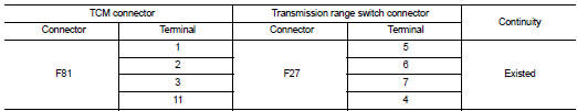
1. CHECK HARNESS BETWEEN TCM AND TRANSMISSION RANGE SWITCH
1. Turn ignition switch OFF.
2. Disconnect TCM connector and transmission range switch connector.
3. Check continuity between TCM connector terminals and transmission range switch connector terminals.
4. If OK, check harness for short to ground and short to power.
5. Reinstall any part removed.
Is the inspection result normal? YES >> GO TO 2.
NO >> Repair or replace damaged parts.
2. DETECT MALFUNCTIONING ITEM
Check the following items.
• Harness for short or open between ignition switch and transmission range switch.
• 10A fuse (No. 55, located in the IPDM E/R).
• Ignition switch.
Is the inspection result normal? YES >> GO TO 3.
NO >> Repair or replace damaged parts.
3. CHECK TRANSMISSION RANGE SWITCH
Check transmission range switch. Refer to TM-201, "Component Inspection".
Is the inspection result normal? YES >> GO TO 4.
NO >> Repair or replace damaged parts.
4.CHECK TCM
Check TCM input/output signals. Refer to TM-164, "Reference Value".
Is the inspection result normal? YES >> Check intermittent incident. Refer to GI-42, "Intermittent Incident".
NO >> Replace the TCM. Refer to TM-280, "Removal and Installation".
Component Inspection
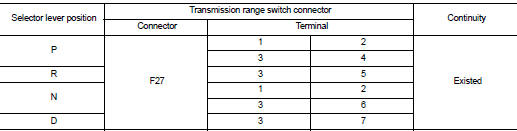
1.CHECK TRANSMISSION RANGE SWITCH
Check continuity between transmission range switch connector terminals.
Is the inspection result normal? YES >> INSPECTION END
NO >> GO TO 2.
2.CHECK CVT POSITION
1. Disconnect control cable.
2. Check transmission range switch. (Refer to step 1 above.) Is the inspection result normal? YES >> Adjust CVT position. Refer to TM-194, "Inspection and Adjustment".
NO >> GO TO 3.
3.CHECK TRANSMISSION RANGE SWITCH
1. Remove transmission range switch. Refer to TM-278, "Removal and Installation".
2. Check transmission range switch. (Refer to step 1 above.) Is the inspection result normal? YES >> Adjust transmission range switch. Refer to TM-278, "Inspection and Adjustment".
NO >> Replace transmission range switch. Refer to TM-278, "Removal and Installation".
 P0703 brake switch B
Description
BCM detects ON/OFF state of the stop lamp switch and transmits the data to
the CVT control unit via CAN
communication by converting the data to a signal.
DTC Logic
DTC DETECTION LOGI ...
 P0710 transmission fluid temperature sensor A
DTC Logic
DTC DETECTION LOGIC
DTC CONFIRMATION PROCEDURE
CAUTION:
Always drive vehicle at a safe speed.
NOTE:
If “DTC CONFIRMATION PROCEDURE” has been previously performed, always turn
ignit ...
Other materials:
B1066, B1071 passenger air bag module
DTC Logic
DTC DETECTION LOGIC
DTC CONFIRMATION PROCEDURE
1.CHECK SELF-DIAG RESULT
With CONSULT-III
1. Turn ignition switch ON.
2. Perform “Self Diagnostic Result” mode of “AIR BAG” using CONSULT-III.
Without CONSULT-III
1. Turn ignition switch ON.
2. Check the air bag warning lamp statu ...
Precautions on seat belt usage
If you are wearing your seat belt properly adjusted, and you are sitting upright
and well back in your seat with both feet on the floor, your chances of being injured
or killed in an accident and/or the severity of injury may be greatly reduced. NISSAN
strongly encourages you and all of your p ...
Condenser
Exploded View
1. Condenser
2. Refrigerant pressure sensor
3. O-ring
4. Grommet
5. Braket
6. O-ring
7. Liquid tank braket
8. Liquid tank
: Do not reuse
: N·m (kg-m, in-lb)
: N·m (kg-m, ft-lb)
Condenser : Removal and Installation
CAUTION:
Perform lubricant return operation before ...
