Nissan Juke Service and Repair Manual : P0560 battery voltage
DTC Logic
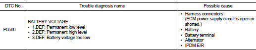
DTC DETECTION LOGIC
NOTE
:
When IPDM E/R DTC is indicated with DTC P0560, IPDM E/R DTC must be checked
first.
Diagnosis Procedure
1.CHECK BATTERY VOLTAGE
1. Turn ignition switch ON.
2. Check battery voltage.
Voltage: Above 11 V
Is the inspection result normal? YES >> GO TO 2.
NO >> Recharge the battery.
2.CHECK BATTERY TERMINALS
1. Turn ignition switch OFF.
2. Check battery terminals condition.
Is the inspection result normal? YES >> GO TO 3.
NO >> Repair the battery terminals.
3.CHECK BATTERY AND ALTERNATOR
Check that the proper type of battery and type of alternator are installed.
Refer to, PG-126, "Battery" and CHG-35, "Alternator".
Is the inspection result normal? YES >> GO TO 4.
NO >> Replace with a proper one.
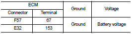
4.CHECK ECM POWER SUPPLY CIRCUIT-I
Check the voltage between ECM harness connector and ground.
Is the inspection result normal? YES >> GO TO 8.
NO >> GO TO 5.
5.CHECK ECM POWER SUPPLY CIRCUIT-II
1. Disconnect ECM harness connector.
2. Disconnect IPDM E/R harness connector E14.
3. Check the continuity between ECM harness connector and IPDM E/R harness connector
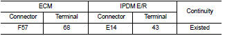
4. Also check harness for short to ground and short to power.
Is the inspection result normal? YES >> GO TO 7.
NO >> GO TO 6.
6.DETECT MALFUNCTIONING PART
Check the following.
• Harness connectors E8, F1 • Harness for open or short between ECM and IPDM E/R
>> Repair open circuit or short to ground or short to power in harness or connectors.
7.CHECK 20A FUSE
1. Disconnect 20A fuse (No. 43) from IPDM E/R.
2. Check 20A fuse.
Is the inspection result normal? YES >> GO TO 8.
NO >> Replace 20A fuse.
8.CHECK INTERMITTENT INCIDENT
Refer to GI-42, "Intermittent Incident", ???INCIDENT SIMULATION TESTS??? and ???GROUND INSPECTION???.
Is the inspection result normal? YES >> Replace IPDM E/R.
NO >> Repair or replace.
 P0544 EGT sensor 1
DTC Logic
DTC DETECTION LOGIC
Diagnosis Procedure
1.CHECK GROUND CONNECTIONS
1. Turn ignition switch OFF.
2. Check ground connection E38. Refer to Ground inspection in GI-44, "Circuit
In ...
 P0564 ASCD steering switch
DTC Logic
DTC DETECTION LOGIC
Diagnosis Procedure
1.CHECK ASCD STEERING SWITCH CIRCUIT
1. Check ASCD steering switch circuit.
ASCD steering switch>>Refer to EC-1011, "Component Fun ...
Other materials:
Blower fan resistor
Exploded View
1. A/C unit assembly
2. Fan control amp.*1
3. Blower fan resistor*2
4. Blower motor
5. Blower motor cover
• *1: Automatic air conditioner
• *2: Manual air conditioner
Removal and Installation
REMOVAL
1. Remove instrument panel assembly. Refer to IP-13, "Removal and ...
B1138, B1139, B1140, B1141, B1142, B1143 diagnosis sensor unit
DTC Logic
DTC DETECTION LOGIC
DTC CONFIRMATION PROCEDURE
1.CHECK SELF-DIAG RESULT
With CONSULT-III
1. Turn ignition switch ON.
2. Perform “Self Diagnostic Result” mode of “AIR BAG” using CONSULT-III.
Without CONSULT-III
1. Turn ignition switch ON.
2. Check the air bag warning lamp statu ...
EPS warning lamp
Component Function Check
1.CHECK THE ILLUMINATION OF THE EPS WARNING LAMP
Check that the EPS warning lamp turns ON when ignition switch turns ON. Then,
EPS warning lamp turns
OFF after the engine is started.
Is the inspection result normal?
YES >> INSPECTION END
NO >> Perform t ...
