Nissan Juke Service and Repair Manual : P0524 engine oil pressure
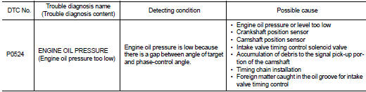
DTC Logic
DTC DETECTION LOGIC
NOTE
:
If DTC P0524 is displayed with DTC P0520, P0075, or P0081, perform trouble
diagnosis for DTC P0520,
P0075, or P0081 first. Refer to EC-176, "DTC Logic".
DTC CONFIRMATION PROCEDURE
1.PRECONDITIONING
If DTC Confirmation Procedure has been previously conducted, always perform the following procedure before conducting the next test.
1. Turn ignition switch OFF and wait at least 10 seconds.
2. Turn ignition switch ON.
3. Turn ignition switch OFF and wait at least 10 seconds.
TESTING CONDITION:
Before performing the following procedure, confirm that battery voltage is
between 10 V and 16 V at
idle.
>> GO TO 2.
2.PRECONDITIONING-II
Check oil level and oil pressure. Refer to LU-8, "Inspection".
Is the inspection result normal? YES >> GO TO 3.
NO >> Proceed to LU-8, "Inspection".
3.PERFORM DTC CONFIRMATION PROCEDURE
 WITH CONSULT-III
1. Select “DATA MONITOR” mode of “ENGINE” using CONSULT-III.
2. Maintain the following conditions for at least 20 consecutive seconds.
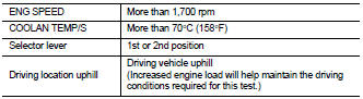
CAUTION:
Always drive at a safe speed.
3. Check 1st trip DTC.
 WITH GST
Follow the procedure “With CONSULT-III” above.
Is 1st trip DTC detected? YES >> Proceed to EC-298, "Diagnosis Procedure" NO >> INSPECTION END
Diagnosis Procedure
1.CHECK OIL PRESSURE WARNING LAMP
1. Start engine.
2. Check oil pressure warning lamp and confirm it is not illuminated.
Is oil pressure warning lamp illuminated? YES >> Proceed to MWI-66, "Diagnosis Procedure".
NO >> GO TO 2.
2.CHECK INTAKE VALVE TIMING CONTROL SOLENOID VALVE
Refer to EC-164, "Component Inspection".
Is the inspection result normal? YES >> GO TO 3.
NO >> Replace malfunctioning intake valve timing control solenoid valve. Refer to EM-67, "Exploded View".
3.CHECK CRANKSHAFT POSITION SENSOR
Refer to EC-273, "Component Inspection".
Is the inspection result normal? YES >> GO TO 4.
NO >> Replace crankshaft position sensor. Refer to EM-78, "Exploded View".
4.CHECK CAMSHAFT POSITION SENSOR
Refer to EC-276, "Component Inspection".
Is the inspection result normal? YES >> GO TO 5.
NO >> Replace malfunctioning camshaft position sensor. Refer to EM-78, "Exploded View".
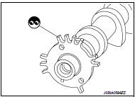
5.CHECK CAMSHAFT (INT)
Check the following.
• Accumulation of debris to the signal plate of camshaft rear end • Chipping signal plate of camshaft rear end
Is the inspection result normal? YES >> GO TO 6.
NO >> Remove debris and clean the signal plate of camshaft rear end or replace camshaft. Refer to EM-79, "Removal and Installation".
6.CHECK TIMING CHAIN INSTALLATION
Check service records for any recent repairs that may cause timing chain misaligned.
Are there any service records that may cause timing chain misaligned? YES >> Check timing chain installation. Refer to EM-67, "Exploded View".
NO >> GO TO 7.
7.CHECK LUBRICATION CIRCUIT
Perform “Inspection of Camshaft Sprocket (INT) Oil Groove”. Refer to EM-82, "Inspection".
Is the inspection result normal? YES >> Check intermittent incident. refer to GI-42, "Intermittent Incident".
NO >> Clean lubrication line.
 P0520 EOP sensor
DTC Logic
DTC CONFIRMATION PROCEDURE
1.PRECONDITIONING
If DTC Confirmation Procedure has been previously conducted, always perform
the following procedure
before conducting the next test.
1. ...
 P0603 ECM power supply
DTC Logic
DTC DETECTION LOGIC
DTC CONFIRMATION PROCEDURE
1.PRECONDITIONING
If DTC Confirmation Procedure has been previously conducted, always perform
the following procedure
before conductin ...
Other materials:
Wiring diagram
BRAKE CONTROL SYSTEM
Wiring Diagram
For connector terminal arrangements, harness layout, and alphabets in a
(option abbreviation; if not
described in wiring diagram), refer to GI-12, "Connector Information/Explanation
of Option Abbreviation".
...
Ambient sensor
Removal and Installation
REMOVAL
1. Remove bumper fascia assembly. Refer to EXT-13, "Removal and
Installation".
2. Disengage fixing pawl, and then remove ambient sensor (1)
from air guide RH.
: Pawl
3. Disconnect ambient sensor connector (2), and then remove
ambient sensor.
INS ...
P173A 2GR incorrect ratio
DTC Logic
DTC DETECTION LOGIC
DTC COFIRMATION PROCEDURE
CAUTION:
• Be sure to perform "TM-444, "Diagnosis Procedure"" and then perform "DTC
CONFIRMATION PROCEDURE".
• Never perform "TC CONFIRMATION PROCEDURE" before the repairs. Doing so may
result ...
