Nissan Juke Service and Repair Manual : P0500 VSS
Description
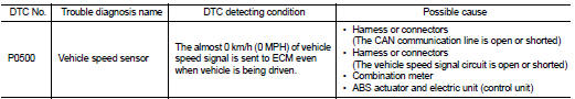
The vehicle speed signal is sent to the combination meter from the “ABS actuator and electric unit (control unit)” by CAN communication line. The combination meter then sends a signal to the ECM by CAN communication line.
DTC Logic
DTC DETECTION LOGIC
NOTE
:
• If DTC P0500 is displayed with DTC U1001, first perform the trouble diagnosis
for DTC U1001. Refer
to EC-569, "DTC Logic".
• If DTC P0500 is displayed with DTC P0607, first perform the trouble diagnosis for DTC P0607. Refer to EC-685, "DTC Logic".
DTC CONFIRMATION PROCEDURE
1.INSPECTION START
Do you have CONSULT-III? Do you have CONSULT-III? YES >> GO TO 2.
NO >> GO TO 5.
2.PRECONDITIONING
If DTC Confirmation Procedure has been previously conducted, always turn ignition switch OFF and wait at least 10 seconds before conducting the next test.
>> GO TO 3.
3.CHECK VEHICLE SPEED SENSOR FUNCTION
NOTE:
This procedure may be conducted with the drive wheels lifted in the shop or by driving the vehicle. If a road test is expected to be easier, it is unnecessary to lift the vehicle.
 With CONSULT-III
1. Start engine.
2. Read “VHCL SPEED SE” in “DATA MONITOR” mode with CONSULT-III. The vehicle speed on CONSULT- III should exceed 10 km/h (6 mph) when rotating wheels with suitable gear position.
Is the inspection result normal? YES >> GO TO 4.
NO >> Go to EC-673, "Diagnosis Procedure".
4.PERFORM DTC CONFIRMATION PROCEDURE
1. Select “DATA MONITOR” mode with CONSULT-III.
2. Warm engine up to normal operating temperature.
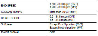
3. Maintain the following conditions for at least 60 consecutive seconds.
CAUTION:
Always drive vehicle at a safe speed.
4. Check 1st trip DTC.
Is 1st trip DTC detected? YES >> Go to EC-673, "Diagnosis Procedure".
NO >> INSPECTION END
5.PERFORM COMPONENT FUNCTION CHECK
Perform component function check. Refer to EC-673, "Component Function Check".
Use component function check to check the overall function of the vehicle speed signal circuit. During this check, a 1st trip DTC might not be confirmed.
Is the inspection result normal? YES >> INSPECTION END NO >> Go to EC-673, "Diagnosis Procedure".
Component Function Check
1.PERFORM COMPONENT FUNCTION CHECK
 With GST
1. Lift up drive wheels.
2. Start engine.
3. Read vehicle speed signal in Service $01 with GST.
The vehicle speed signal on GST should be able to exceed 10 km/h (6 MPH) when rotating wheels with suitable gear position.
Is the inspection result normal? YES >> INSPECTION END
NO >> Go to EC-673, "Diagnosis Procedure".
Diagnosis Procedure
1.CHECK DTC WITH ABS ACTUATOR AND ELECTRIC UNIT (CONTROL UNIT) Check DTC with ABS actuator and electric unit (control unit). Refer to BRC-31, "DTC Index" (Without EPS) or BRC-142, "DTC Index" (With EPS).
Is the inspection result normal? YES >> GO TO 2.
NO >> Repair or replace.
2.CHECK DTC WITH COMBINATION METER
Check DTC with combination meter. Refer to MWI-36, "DTC Index".
>> INSPECTION END
 P0444 EVAP canister purge volume control solenoid valve
DTC Logic
DTC DETECTION LOGIC
DTC CONFIRMATION PROCEDURE
1.CONDITIONING
If DTC Confirmation Procedure has been previously conducted, always turn
ignition switch OFF and wait at
least 10 secon ...
 P0520 EOP sensor
DTC Logic
DTC DETECTION LOGIC
DTC CONFIRMATION PROCEDURE
1.PRECONDITIONING
If DTC Confirmation Procedure has been previously conducted, always perform
the following procedure
before conductin ...
Other materials:
Floor trim
Exploded View
LHD models
1. Floor carpet
2. Carpet hook
3. Trim clip
4. Column hole cover
5. Harness clip
6. Front floor spacer RH
7. Front floor spacer LH
8. Rear floor spacer LH
9. Rear floor spacer RH
: Clip
: Pawl
Removal and Installation
REMOVAL
CAUTION:
• When removing ...
Audio unit
Removal and Installation
REMOVAL
1. Remove cluster lid C. Refer to IP-12, "Exploded View".
2. Remove audio unit screws.
3. Disconnect audio unit connectors to remove audio unit and brackets as a
single unit.
4. Remove brackets screws to remove audio unit.
INSTALLATION
1. Install ...
Precaution Necessary for Steering Wheel Rotation after Battery Disconnect
NOTE:
• Before removing and installing any control units, first turn the ignition
switch to the LOCK position, then disconnect
both battery cables.
• After finishing work, confirm that all control unit connectors are connected
properly, then re-connect both
battery cables.
• Always use CONS ...
