Nissan Juke Service and Repair Manual : P0403 EGR volume control valve
DTC Logic
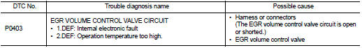
DTC DETECTION LOGIC
Diagnosis Procedure
1.CHECK EGR VOLUME CONTROL VALVE CONTROL CIRCUIT
1. Turn ignition switch OFF.
2. Disconnect EGR volume control valve harness connector and ECM harness connector.
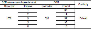
3. Check the continuity between EGR volume control valve terminal harness connector and ECM harness connector
4. Also check harness for short to ground and short to power.
OK or NG OK >> GO TO 2.
NG >> Repair open circuit or short to ground or short to power in harness or connectors.
2.CHECK EGR VOLUME CONTROL VALVE
Refer to EC-941, "Component Inspection".
OK or NG OK >> GO TO 3.
NG >> Replace EGR volume control valve.
3.CHECK EGR VOLUME CONTROL VALVE CONTROL POSITION SENSOR
Refer to EC-941, "Component Inspection".
OK or NG OK >> GO TO 4.
NG >> Replace EGR volume control valve.
4.CHECK EGR PASSAGE
Check the following for clogging and cracks.
• EGR tube
• EGR hose
• EGR cooler
OK or NG OK >> GO TO 5.
NG >> Repair or replace EGR passage.
5.CHECK INTERMITTENT INCIDENT
Refer to GI-42, "Intermittent Incident".
>> INSPECTION END
Component Inspection
EGR VOLUME CONTROL VALVE
1. Disconnect EGR volume control valve harness connector.
2. Check resistance EGR volume control valve harness connector.
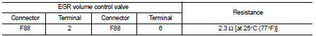
If NG, replace EGR volume control valve. Refer to EC-881, "Work Procedure".
EGR VOLUME CONTROL VALVE CONTROL POSITION SENSOR
1. Disconnect EGR volume control valve harness connector.
2. Check continuity EGR volume control valve harness connector.
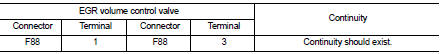
If NG, replace EGR volume control valve. Refer to EC-881, "Work Procedure".
 P0402 EGR volume control valve
DTC Logic
DTC DETECTION LOGIC
Diagnosis Procedure
1.CHECK GROUND CONNECTIONS
1. Turn ignition switch OFF.
2. Check ground connection E38. Refer to Ground inspection in GI-44, "Circuit
In ...
 P0409 EGR volume control valve control position sensor
DTC Logic
DTC DETECTION LOGIC
Diagnosis Procedure
1.CHECK GROUND CONNECTIONS
1. Turn ignition switch OFF.
2. Check ground connection E38. Refer to Ground inspection in GI-44, "Circuit
In ...
Other materials:
Glow plug
Exploded View
1. Glow plug
Engine front
: N·m (kg-m, ft-lb)
Removal and Installation
REMOVAL
CAUTION:
Remove glow plug only if necessary. If carbon adheres, it may be stuck and
broken.
1. Disconnect the battery cable from the negative terminal.
2. Remove cowl top extension. Refer to EX ...
Fuel level sensor unit
Exploded View
1. Lock ring
2. Fuel level sensor unit
3. Seal packing
A. To fuel tank
: Always replace after every
disassembly
Removal and Installation
WARNING:
Read “General Precautions” when working on the fuel system. Refer to FL-45,
"General Precautions".
REMOVAL
1. Ch ...
B2098 ignition relay on stuck
Description
The ignition relay integrated in IPDM E/R is operated with ignition switch ON
signal from the ignition switch.
DTC Logic
DTC DETECTION LOGIC
1.PERFORM DTC CONFIRMATION PROCEDURE
1. Turn ignition switch ON.
2. Check DTC in “Self Diagnostic Result” mode of “IPDM E/R” using CONSUL ...
