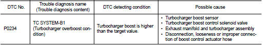
Nissan Juke Service and Repair Manual : P0234 TC system
DTC Logic
DTC DETECTION LOGIC
NOTE
:
If DTC P0234 is displayed with DTC P0237 or P0238, first perform the trouble
diagnosis for DTC P0237 or
P0238. Refer to EC-260, "DTC Logic".
DTC CONFIRMATION PROCEDURE
1.PERFORM COMPONENT FUNCTION CHECK
Perform component function check. Refer to EC-257, "Component Function Check".
NOTE
:
Use component function check to check the overall function of the turbocharger
system circuit. During this
check, DTC might not be confirmed.
Is the inspection result normal? YES >> INSPECTION END NO >> Proceed to EC-258, "Diagnosis Procedure".
Component Function Check
1.CHECK BOOST CONTROL ACTUATOR HOSE
Check disconnection, looseness or improper connection of hose between turbocharger boost control solenoid valve and boost control actuator.
Is the inspection result normal? YES >> GO TO 2.
NO >> Proceed to EC-258, "Diagnosis Procedure".
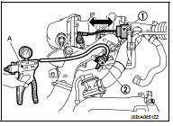
2.PERFORM COMPONENT FUNCTION CHECK
1. Turn ignition switch OFF.
2. Disconnect turbocharger boost control solenoid valve harness connector.
3. Disconnect of hose between turbocharger boost control solenoid valve and compressor wheel.
4. Install pressure pump to turbocharger boost control solenoid valve.
5. Check that the rod of the boost control actuator activates when supplying pressure and battery voltage to the turbocharger boost control solenoid valve as per the following conditions
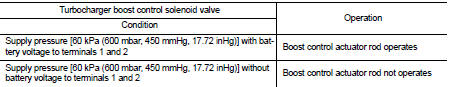
CAUTION:
Do not supply pressure over 70 kPa (700 mbar, 525 mmHg, 20.67 inHg)
Is the inspection result normal? YES >> INSPECTION END
NO >> Proceed to EC-258, "Diagnosis Procedure".
Diagnosis Procedure
1.CHECK BOOST CONTROL ACTUATOR HOSE
Check disconnection, looseness or improper connection of hose between turbocharger boost control solenoid valve and boost control actuator.
Is the inspection result normal? YES >> GO TO 2.
NO >> Repair or replace error-detected parts.
2.CHECK TURBOCHARGER BOOST CONTROL SOLENOID VALVE POWER SUPPLY
1. Turn ignition switch OFF.
2. Disconnect turbocharger boost control solenoid valve harness connector.
3. Turn ignition switch ON.
4. Check the voltage between turbocharger boost control solenoid valve harness connector and ground.
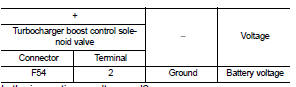
Is the inspection result normal? YES >> GO TO 4.
NO >> GO TO 3.
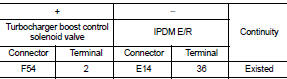
3.CHECK TURBOCHARGER BOOST CONTROL SOLENOID VALVE POWER SUPPLY CIRCUIT
1. Turn ignition switch OFF.
2. Disconnect IPDM E/R harness connector.
3. Check the continuity between turbocharger boost control solenoid valve harness connector and IPDM E/R harness connector.
4. Also check harness for short to ground and short.
Is the inspection result normal? YES >> Perform the trouble diagnosis for power supply circuit.
NO >> Repair or replace error-detected parts.
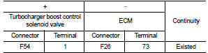
4.CHECK TURBOCHARGER BOOST CONTROL SOLENOID VALVE GROUND CIRCUIT
1. Turn ignition switch OFF.
2. Disconnect ECM harness connector.
3. Check the continuity between turbocharger boost control solenoid valve harness connector and ECM harness connector.
4. Also check harness for short to power.
Is the inspection result normal? YES >> GO TO 5.
NO >> Repair or replace error-detected parts.
5.CHECK TURBOCHARGER BOOST CONTROL SOLENOID VALVE
Check the turbocharger boost control solenoid valve. Refer to EC-175, "Component Inspection".
Is the inspection result normal? YES >> GO TO 6.
NO >> Replace turbocharger boost control solenoid valve. Refer to EM-36, "Exploded View".
6.CHECK BOOST CONTROL ACTUATOR
Check the boost control actuator. Refer to EM-37, "Inspection".
Is the inspection result normal? YES >> GO TO 7.
NO >> Replace exhaust manifold and turbocharger assembly. Refer to EM-36, "Exploded View".
7.CHECK TURBOCHARGER BOOST SENSOR
Check the turbocharger boost sensor. Refer to EC-262, "Component Inspection".
Is the inspection result normal? YES >> Check intermittent incident. Refer to GI-42, "Intermittent Incident".
NO >> Replace turbocharger boost sensor. Refer to EM-31, "Exploded View".
 P0222, P0223 TP sensor
DTC Logic
DTC DETECTION LOGIC
NOTE:
If DTC P0222 or P0223 is displayed with DTC P0643 ,first perform the trouble
diagnosis for DTC P0643.
Refer to EC-274, "DTC Logic".
DTC CONFIRM ...
 P0237, P0238 TC boost sensor
DTC Logic
DTC DETECTION LOGIC
DTC CONFIRMATION PROCEDURE
1.PRECONDITIONING
If DTC Confirmation Procedure has been previously conducted, always perform
the following procedure
before conductin ...
Other materials:
Precaution for Supplemental Restraint System (SRS) "AIR BAG" and "SEAT BELT
PRE-TENSIONER"
The Supplemental Restraint System such as “AIR BAG” and “SEAT BELT
PRE-TENSIONER”, used along
with a front seat belt, helps to reduce the risk or severity of injury to the
driver and front passenger for certain
types of collision. Information necessary to service the system safely is
include ...
Removal and installation
PUSH-BUTTON IGNITION SWITCH
Removal and Installation
REMOVAL
1. Remove the NATS antenna amp. Refer to SEC-167, "Removal and
Installation".
2. Remove the push-button ignition switch.
1. Disengage the push-button ignition switch fixing pawls
using minus driver etc.
2. Press the pu ...
AWD warning light
The AWD warning light located in the instrument panel illuminates when the ignition
switch is turned to the ON position. It turns off soon after the engine is started.
If any malfunction occurs in the AWD system while the engine is running, or while
driving, the warning light will either rema ...
