Nissan Juke Service and Repair Manual : P0225 APP sensor
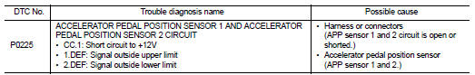
DTC Logic
DTC DETECTION LOGIC
NOTE
:
• If DTC P0225 is displayed with DTC P0641, first perform trouble diagnosis for
DTC P0641. Refer to
EC-974, "DTC Logic".
Diagnosis Procedure
1.CHECK GROUND CONNECTIONS
1. Turn ignition switch OFF.
2. Check ground connection E38. Refer to Ground inspection in GI-44, "Circuit Inspection".
Is the inspection result normal? YES >> GO TO 2.
NO >> Repair or replace ground connection.
2.CHECK ACCELERATOR PEDAL POSITION SENSOR POWER SUPPLY CIRCUIT
1. Disconnect accelerator pedal position sensor harness connector.
2. Turn ignition switch ON.
3. Check the voltage between accelerator pedal position sensor connector and ground
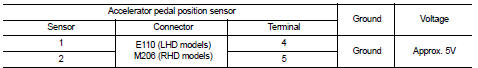
Is the inspection result normal? YES >> GO TO 4.
NO >> GO TO 3.
3.DETECT MALFUNCTIONING PART
• Harness connectors M77, E105 (RHD models) • Harness connectors M95, M202 (RHD models) • Harness for open or short between ECM and accelerator pedal position sensor
>> Repair open circuit or short to ground or short to power in harness or connector.
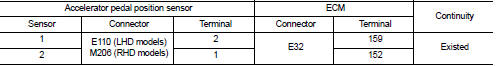
4.CHECK ACCELERATOR PEDAL POSITION SENSOR GROUND CIRCUIT FOR OPEN AND SHORT
1. Turn ignition switch OFF.
2. Disconnect ECM harness connector.
3. Check the continuity between accelerator pedal position sensor harness connector and ECM harness connector.
4. Also check harness for short to ground and short to power.
Is the inspection result normal? YES >> GO TO 6.
NO >> GO TO 5.
5.DETECT MALFUNCTIONING PART
• Harness connectors M77, E105 (RHD models) • Harness connectors M95, M202 (RHD models) • Harness for open or short between ECM and accelerator pedal position sensor
>> Repair open circuit or short to ground or short to power in harness or connector.
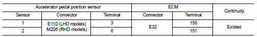
6.CHECK ACCELERATOR PEDAL POSITION SENSOR INPUT SIGNAL CIRCUIT FOR OPEN AND SHORT
1. Check the continuity between accelerator pedal position sensor harness connector and ECM harness connector.
2. Also check harness for short to ground and short to power.
Is the inspection result normal? YES >> GO TO 8.
NO >> GO TO 7.
7.DETECT MALFUNCTIONING PART
• Harness connectors M77, E105 (RHD models) • Harness connectors M95, M202 (RHD models) • Harness for open or short between ECM and accelerator pedal position sensor
>> Repair open circuit or short to ground or short to power in harness or connector.
8.CHECK ACCELERATOR PEDAL POSITION SENSOR
Refer to EC-926, "Component Inspection".
Is the inspection result normal? YES >> GO TO 9.
NO >> Replace accelerator pedal position sensor.
9.CHECK INTERMITTENT INCIDENT
Refer to GI-42, "Intermittent Incident", ???INCIDENT SIMULATION TESTS??? and ???GROUND INSPECTION???.
>> INSPECTION END
Component Inspection
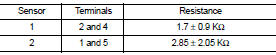
1.CHECK ACCELERATOR PEDAL POSITION SENSOR
1. Turn ignition switch OFF.
2. Disconnect accelerator pedal position sensor harness connector.
3. Check resistance between accelerator pedal position sensor as follows.
Is the inspection result normal?
YES >> INSPECTION END
NO >> Replace accelerator pedal position sensor.
 P0217 engine over temperature
DTC Logic
DTC DETECTION LOGIC
If the cooling fan or another component in the cooling system malfunctions,
engine coolant temperature will
rise.
When the engine coolant temperature reaches an a ...
 P0226 APP sensor
DTC Logic
DTC DETECTION LOGIC
Diagnosis Procedure
1.CHECK GROUND CONNECTIONS
1. Turn ignition switch OFF.
2. Check ground connection E38. Refer to Ground inspection in GI-44, "Circuit
In ...
Other materials:
Water outlet
Exploded View
1. Heater pipe bracket
2. Radiator cap
3. Water outlet adaptor
4. Clamp
5. Water outlet hose
6. Clamp
7. Heater hose
8. Clamp
9. Water outlet
10. Clamp
11. Heater hose
12. Heater hose
13. Clamp
14. Heater hose
15. Clamp
16. Engine coolant temperature sensor ...
Precaution Necessary for Steering Wheel Rotation
after Battery Disconnect
NOTE:
• Before removing and installing any control units, first turn the push-button
ignition switch to the LOCK position,
then disconnect both battery cables.
• After finishing work, confirm that all control unit connectors are connected
properly, then re-connect both
battery cables.
• Alw ...
Vehicle security system cannot be set
Key fob
KEY FOB : Description
Armed phase is not activated when door is locked using keyfob.
NOTE:
Check that vehicle is under the condition shown in “CONDITIONS OF VEHICLE
(OPERATING CONDITIONS)”
before starting diagnosis, and check each symptom.
CONDITION OF VEHICLE (OPERATING CONDITIO ...
