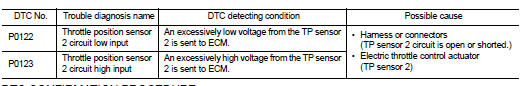
Nissan Juke Service and Repair Manual : P0122, P0123 TP SENSOR
DTC Logic
DTC DETECTION LOGIC
NOTE
:
If DTC P0122 or P0123 is displayed with DTC P0643, first perform the trouble
diagnosis for DTC P0643.
Refer to EC-686, "DTC Logic".
DTC CONFIRMATION PROCEDURE
1.PRECONDITIONING
If DTC Confirmation Procedure has been previously conducted, always turn ignition switch OFF and wait at least 10 seconds before conducting the next test.
TESTING CONDITION:
Before performing the following procedure, confirm that battery voltage is more
than 10 V at idle.
>> GO TO 2.
2.PERFORM DTC CONFIRMATION PROCEDURE
1. Start engine and let it idle for 1 second.
2. Check DTC.
Is DTC detected? YES >> Go to EC-597, "Diagnosis Procedure".
NO >> INSPECTION END
Diagnosis Procedure
1.CHECK GROUND CONNECTION
1. Turn ignition switch OFF.
2. Check ground connection E21 and E38. Refer to Ground Inspection in GI-44, "Circuit Inspection".
Is the inspection result normal? YES >> GO TO 2.
NO >> Repair or replace ground connection.
2.CHECK THROTTLE POSITION SENSOR 2 POWER SUPPLY CIRCUIT
1. Disconnect electric throttle control actuator harness connector.
2. Turn ignition switch ON.
3. Check the voltage between electric throttle control actuator harness connector and ground.
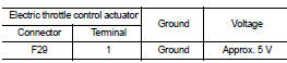
Is the inspection result normal? YES >> GO TO 3.
NO >> Repair open circuit or short to ground or short to power in harness or connectors.
3.CHECK THROTTLE POSITION SENSOR 2 GROUND CIRCUIT FOR OPEN AND SHORT
1. Turn ignition switch OFF.
2. Disconnect ECM harness connector.
3. Check the continuity between electric throttle control actuator harness connector and ECM harness connector.
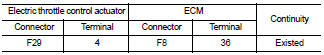
4. Also check harness for short to ground and short to power.
Is the inspection result normal? YES >> GO TO 4.
NO >> Repair open circuit or short to ground or short to power in harness or connectors.
4.CHECK THROTTLE POSITION SENSOR 2 INPUT SIGNAL CIRCUIT FOR OPEN AND SHORT
1. Check the continuity between electric throttle control actuator harness connector and ECM harness connector.
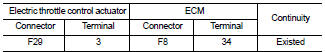
2. Also check harness for short to ground and short to power.
Is the inspection result normal? YES >> GO TO 5.
NO >> Repair open circuit or short to ground or short to power in harness or connectors.
5.CHECK THROTTLE POSITION SENSOR
Refer to EC-598, "Component Inspection".
Is the inspection result normal? YES >> GO TO 7.
NO >> GO TO 6.
6.REPLACE ELECTRIC THROTTLE CONTROL ACTUATOR
Replace electric throttle control actuator. Refer to EM-163, "Exploded View".
>> INSPECTION END 7.CHECK INTERMITTENT INCIDENT
Refer to GI-42, "Intermittent Incident".
>> INSPECTION END
Component Inspection
1.CHECK THROTTLE POSITION SENSOR
1. Turn ignition switch OFF.
2. Reconnect all harness connectors disconnected.
3. Perform EC-543, "Work Procedure".
4. Turn ignition switch ON.
5. Set selector lever to D (CVT) or 1st (M/T) position.
6. Check the voltage between ECM harness connector and ground.
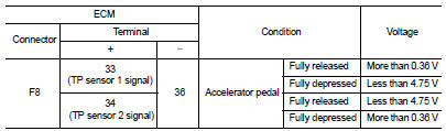
Is the inspection result normal? YES >> INSPECTION END
NO >> GO TO 2.
2.REPLACE ELECTRIC THROTTLE CONTROL ACTUATOR
Replace electric throttle control actuator. Refer to EM-163, "Exploded View".
>> INSPECTION END
 P0117, P0118 ECT SENSOR
DTC Logic
DTC DETECTION LOGIC
DTC CONFIRMATION PROCEDURE
1.PRECONDITIONING
If DTC Confirmation Procedure has been previously conducted, always turn
ignition switch OFF and wait at
least 10 se ...
 P0130 A/F sensor 1
DTC Logic
DTC DETECTION LOGIC
To judge malfunctions, the diagnosis checks that the A/F signal computed by
ECM from the A/F sensor 1 signal
fluctuates according to fuel feedback control.
DTC CO ...
Other materials:
Mixture ratio self-learning value clear
Description
This describes how to erase the mixture ratio self-learning value. For the
actual procedure, follow the instructions
in “Diagnosis Procedure”.
Work Procedure
1.START
With CONSULT-III
1. Start engine and warm it up to normal operating temperature.
2. Select “SELF-LEARNING CONT” i ...
Lift gate
WARNING
• Always be sure the lift gate has been closed securely to prevent it from
opening while driving.
• Do not drive with the lift gate open.
This could allow dangerous exhaust gases to be drawn into the vehicle.
See “Exhaust gas (carbon monoxide)” of this manual.
• Do not leave chi ...
Front fog lamp
Exploded View
1. Front fog lamp assembly
2. Metal clip
3. Front fog lamp bulb
4. Front fog lamp bracket
5. U nut
6. Front bumper fascia lower
: Pawl
: N·m (kg-m, in-lb)
Removal and Installation
CAUTION:
Disconnect the battery negative terminal or remove the fuse.
REMOVAL
1. Remove ...
