Nissan Juke Service and Repair Manual : P0078 EVT control solenoid valve
DTC Logic
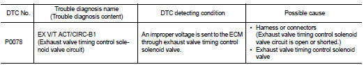
DTC DETECTION LOGIC
DTC CONFIRMATION PROCEDURE
1.PRECONDITIONING
If DTC Confirmation Procedure has been previously conducted, always perform the following procedure before conducting the next test.
1. Turn ignition switch OFF and wait at least 10 seconds.
2. Turn ignition switch ON.
3. Turn ignition switch OFF and wait at least 10 seconds.
>> GO TO2.
2.PERFORM DTC CONFIRMATION PROCED
1. Start engine and let it idle for 5 seconds.
2. Check 1st trip DTC.
Is 1st trip DTC detected? YES >> Proceed to EC-179, "Diagnosis Procedure".
NO >> INSPECTION END
Diagnosis Procedure
1.CHECK EXHAUST VALVE TIMING CONTROL SOLENOID VALVE POWER SUPPLY
1. Turn ignition switch OFF.
2. Disconnect exhaust valve timing (EVT) control solenoid valve harness connector.
3. Turn ignition switch ON.
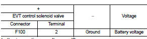
4. Check the voltage between exhaust valve timing control solenoid valve harness connector and ground.
Is the inspection result normal? YES >> GO TO 3.
NO >> GO TO 2.
2.CHECK EXHAUST VALVE TIMING CONTROL SOLENOID VALVE POWER SUPPLY CIRCUIT
1. Turn ignition switch OFF.
2. Disconnect IPDM E/R harness connector.
3. Check the continuity between EVT control solenoid valve harness connector and IPDM E/R harness connector.
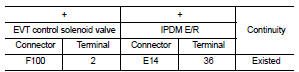
4. Also check harness for short to ground.
Is the inspection result normal? YES >> Perform the trouble diagnosis for power supply circuit.
NO >> Repair or replace error-detected parts.
3.CHECK EXHAUST VALVE TIMING CONTROL SOLENOID VALVE GROUND CIRCUIT
1. Turn ignition switch OFF.
2. Disconnect ECM harness connector.
3. Check the continuity between EVT control solenoid valve harness connector and ECM harness connector.
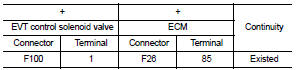
4. Also check harness for short to ground and to power.
Is the inspection result normal? YES >> GO TO 4.
NO >> Repair or replace error-detected parts.
4.CHECK EXHAUST VALVE TIMING CONTROL SOLENOID VALVE
Check the exhaust valve timing control solenoid valve. Refer to EC-177, "Component Inspection".
Is the inspection result normal? YES >> Check intermittent incident. Refer to GI-42, "Intermittent Incident".
NO >> Replace exhaust valve timing control solenoid valve.
Component Inspection
1.CHECK EXHAUST VALVE TIMING CONTROL SOLENOID VALVE-I
1. Turn ignition switch OFF.
2. Disconnect exhaust valve timing control solenoid valve harness connector.
3. Check resistance between exhaust valve timing control solenoid valve terminals as per the following.
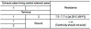
Is the inspection result normal? YES >> GO TO 2.
NO >> Replace exhaust valve timing control solenoid valve. Refer to EM-67, "Exploded View".
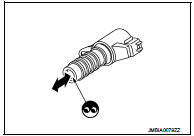
2.CHECK EXHAUST VALVE TIMING CONTROL SOLENOID VALVE-II
1. Remove exhaust valve timing control solenoid valve. Refer to EM-67, "Exploded View".
2. Provide 12 V DC between exhaust valve timing control solenoid valve terminals 1 and 2, and then interrupt it. Check that the plunger moves as shown in the figure.
CAUTION: Do not apply 12 V DC continuously for 5 seconds or more.
Doing so may result in damage to the coil in exhaust valve timing control solenoid valve.
NOTE: Always replace O-ring when exhaust valve timing control solenoid valve is removed.
Is the inspection result normal? YES >> INSPECTION END NO >> Replace exhaust valve timing control solenoid valve. Refer to EM-67, "Exploded View".
 P0075 IVT control solenoid valve
DTC Logic
DTC DETECTION LOGIC
DTC CONFIRMATION PROCEDURE
1.PRECONDITIONING
If DTC Confirmation Procedure has been previously conducted, always perform
the following procedure
before conductin ...
 P0087, P0088, P0090 FRP control system
DTC Logic
DTC DETECTION LOGIC
NOTE:
• If DTC P0087 or P0090 is displayed with DTC P1197, first perform the trouble
diagnosis for DTC
P1197.
• DTC P0087 or P0090 may be displayed when running ou ...
Other materials:
Diagnosis system (BCM) (without intelligent key system)
Common item
COMMON ITEM : CONSULT-III Function (BCM - COMMON ITEM)
APPLICATION ITEM
CONSULT-III performs the following functions via CAN communication with BCM.
SYSTEM APPLICATION
BCM can perform the following functions for each system.
NOTE:
It can perform the diagnosis modes except the fo ...
B1088 seat belt Pre-tensioner LH
DTC Logic
DTC DETECTION LOGIC
DTC CONFIRMATION PROCEDURE
1.CHECK SELF-DIAG RESULT
With CONSULT-III
1. Turn ignition switch ON.
2. Perform “Self Diagnostic Result” mode of “AIR BAG” using CONSULT-III.
Without CONSULT-III
1. Turn ignition switch ON.
2. Check the air bag warning lamp statu ...
System
NISSAN anti-theft system
NISSAN ANTI-THEFT SYSTEM : System Diagram
NISSAN ANTI-THEFT SYSTEM : System Description
SYSTEM DESCRIPTION
Nissan Anti-Theft System (NATS) has the following immobilizer functions:
• NATS shows high anti-theft performance to prevent engine from starting by
anyone oth ...
