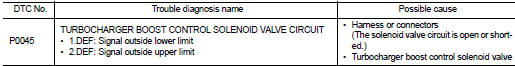
Nissan Juke Service and Repair Manual : P0045 TC boost control solenoid valve
DTC Logic
DTC DETECTION LOGIC
Diagnosis Procedure
1.CHECK TURBOCHARGER BOOST CONTROL SOLENOID VALVE POWER SUPPLY CIRCUIT
1. Turn ignition switch OFF.
2. Disconnect turbocharger boost control solenoid valve harness connector.
3. Turn ignition switch ON.
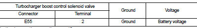
4. Check the voltage between turbocharger boost control solenoid valve harness connector and ground.
Is the inspection result normal? YES >> GO TO 3.
NO >> GO TO 2.
2.DETECT MALFUNCTIONING PART
Check the following.
• Harness for open or short between IPDM E/R and turbocharger boost control solenoid valve
>> Repair open circuit or short to ground or short to power in harness or connectors.
3.CHECK TURBOCHARGER BOOST CONTROL SOLENOID VALVE OUTPUT SIGNAL CIRCUIT FOR OPEN AND SHORT
1. Turn ignition switch OFF.
2. Disconnect ECM harness connector.
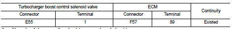
3. Check the continuity between turbocharger boost control solenoid valve harness connector and ECM harness connector.
4. Also check harness for short to ground and short to power.
Is the inspection result normal? YES >> GO TO 4.
NO >> Repair open circuit or short to ground or short to power in harness or connectors.
4.CHECK TURBOCHARGER BOOST CONTROL SOLENOID VALVE
Refer to EC-894, "Component Inspection".
Is the inspection result normal? YES >> GO TO 5.
NO >> Replace turbocharger boost control solenoid valve.
5.CHECK INTERMITTENT INCIDENT
Refer to GI-42, "Intermittent Incident", ???INCIDENT SIMULATION TESTS??? and ???GROUND INSPECTION???.
>> INSPECTION END
Component Inspection
1.CHECK TURBOCHARGER BOOST CONTROL SOLENOID VALVE
1. Turn ignition switch OFF.
2. Disconnect turbocharger boost control solenoid valve harness connector.
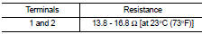
3. Check resistance between turbocharger boost control solenoid valve terminals as follows.
Is the inspection result normal? YES >> INSPECTION END
NO >> Replace turbocharger boost control solenoid valve.
 P0016 CKP - CMP correlation
DTC Logic
DTC DETECTION LOGIC
Diagnosis Procedure
1.CHECK CKP SENSOR AND CMP SENSOR
Refer to EC-932, "Diagnosis Procedure" (CKP sensor) and EC-934, "Diagnosis
Procedure" (C ...
 P0087 fuel pump
DTC Logic
DTC DETECTION LOGIC
NOTE:
• Conditions for applying the diagnostic procedure to the stored DTCs:
The DTC becomes present during the first 30 seconds after the engine starts.
• In low ...
Other materials:
B26F4 starter control relay
DTC Logic
DTC DETECTION LOGIC
NOTE:
• If DTC B26F4 is displayed with DTC U1000, first perform the trouble diagnosis
for DTC U1000. Refer to
BCS-83, "DTC Logic".
• If DTC B26F4 is displayed with DTC U1010, first perform the trouble diagnosis
for DTC U1010. Refer to
BCS-84, "D ...
System (intelligent key system)
Intelligent key system : System Diagram
Intelligent key system : System Description
• The Intelligent Key system is a system that makes it possible to lock and
unlock the door locks (door lock/
unlock function) by carrying the Intelligent Key, which operates based on the
results of electron ...
B2556 Push-button ignition switch
DTC Logic
DTC DETECTION LOGIC
DTC CONFIRMATION PROCEDURE
1.PERFORM DTC CONFIRMATION PROCEDURE
1. Press push-button ignition switch under the following condition.
- Brake pedal: Not depressed
2. Release push-button ignition switch and wait 100 seconds or more.
3. Check DTC in “Self Diagnosti ...
