Nissan Juke Service and Repair Manual : P0014 EVT control
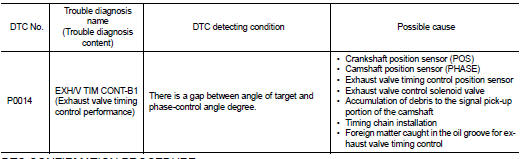
DTC Logic
DTC DETECTION LOGIC
NOTE:
• If DTC P0014 is displayed with DTC P0078, first perform trouble diagnosis for
DTC P0078. Refer to
EC-179, "DTC Logic".
• If DTC P0014 is displayed with P1078, first perform trouble diagnosis for P1078. Refer to EC-313, "DTC Logic"
.
DTC CONFIRMATION PROCEDURE
1.PRECONDITIONING
If DTC Confirmation Procedure has been previously conducted, always perform the following procedure before conducting the next test.
1. Turn ignition switch OFF and wait at least 10 seconds.
2. Turn ignition switch ON.
3. Turn ignition switch OFF and wait at least 10 seconds.
TESTING CONDITION:
Before performing the following procedure, confirm that battery voltage is
between 10 V and 16 V at
idle.
>> GO TO 2.
2.PERFORM DTC CONFIRMATION PROCEDURE-I
 With CONSULT-III
1. Turn ignition switch ON and select “DATA MONITOR” mode of “ENGINE” using CONSULT-III.
2. Start engine and warm it up to the normal operating temperature.
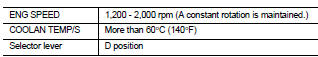
3. Maintain the following conditions for at least 6 consecutive seconds. Hold the accelerator pedal as steady as possible.
4. Let engine idle for 10 seconds.
5. Check 1st trip DTC.
 With GST
Follow the procedure “With CONSULT-III” above.
Is 1st trip DTC detected? YES >> Proceed to EC-166, "Diagnosis Procedure" NO >> GO TO 3.
3.PERFORM DTC CONFIRMATION PROCEDURE-II
With CONSULT-III
1. Select “DATA MONITOR” mode of “ENGINE” using CONSULT-III.
2. Maintain the following conditions for at least 20 consecutive seconds.
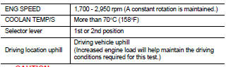
CAUTION:
Always drive at a safe speed.
3. Check 1st trip DTC.
With GST
Follow the procedure “With CONSULT-III” above.
Is 1st trip DTC detected? YES >> Proceed to EC-166, "Diagnosis Procedure"
NO >> INSPECTION END
Diagnosis Procedure
1.CHECK OIL PRESSURE WARNING LAMP
1. Start engine.
2. Check oil pressure warning lamp and confirm it is not illuminated.
Is oil pressure warning lamp illuminated? YES >> Check the engine oil level. Refer to LU-8, "Inspection".
NO >> GO TO 2.
2.CHECK EXHAUST VALVE TIMING CONTROL SOLENOID VALVE
Check the exhaust valve timing control solenoid valve. Refer to EC-164, "Component Inspection".
Is the inspection result normal? YES >> GO TO 3.
NO >> Replace exhaust valve timing control solenoid valve. Refer to EM-67, "Exploded View".
3.CHECK CRANKSHAFT POSITION SENSOR (POS)
Check the crankshaft position sensor (POS). Refer to EC-273, "Component Inspection".
Is the inspection result normal? YES >> GO TO 4.
NO >> Replace crankshaft position sensor (POS). Refer to EM-103, "Exploded View".
4.CHECK EXHAUST VALVE TIMING CONTROL POSITION SENSOR
Check the exhaust valve timing control position sensor. Refer to EC-276, "Component Inspection".
Is the inspection result normal? YES >> GO TO 5.
NO >> Replace exhaust valve timing control position sensor. Refer to EM-78, "Exploded View".
5.CHECK CAMSHAFT (EXH)
Check the following.
• Accumulation of debris to the signal plate of camshaft rear end • Chipping signal plate of camshaft rear end
Is the inspection result normal? YES >> GO TO 6.
NO >> Remove debris and clean the signal plate of camshaft rear end or replace camshaft. Refer to EM-79, "Removal and Installation".
6.CHECK TIMING CHAIN INSTALLATION
Check service records for any recent repairs that may cause timing chain misaligned.
Are there any service records that may cause timing chain misaligned? YES >> Check timing chain installation. Refer to EM-68, "Removal and Installation".
NO >> GO TO 7.
7.CHECK LUBRICATION CIRCUIT
Refer to LU-8, "Inspection".
Is the inspection result normal? YES >> Check intermittent incident. Refer to GI-42, "Intermittent Incident".
NO >> Clean lubrication line.
Component Inspection
1.CHECK EXHAUST VALVE TIMING CONTROL SOLENOID VALVE-I
1. Turn ignition switch OFF.
2. Disconnect exhaust valve timing control solenoid valve harness connector.
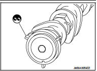
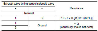
3. Check resistance between exhaust valve timing control solenoid valve terminals as per the following.
Is the inspection result normal? YES >> GO TO 2.
NO >> Replace exhaust valve timing control solenoid valve. Refer to EM-67, "Exploded View".
2.CHECK EXHAUST VALVE TIMING CONTROL SOLENOID VALVE-II
1. Remove exhaust valve timing control solenoid valve. Refer to EM-67, "Exploded View".
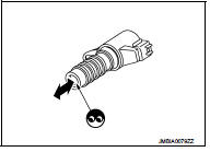
2. Provide 12 V DC between exhaust valve timing control solenoid valve terminals 1 and 2, and then interrupt it. Check that the plunger moves as shown in the figure.
CAUTION:
Do not apply 12 V DC continuously for 5 seconds or more.
Doing so may result in damage to the coil in exhaust valve timing control solenoid valve.
NOTE:
Always replace O-ring when exhaust valve timing control solenoid valve is removed.
Is the inspection result normal? YES >> INSPECTION END
NO >> Replace exhaust valve timing control solenoid valve. Refer to EM-67, "Exploded View".
 P0011 IVT control
DTC Logic
DTC DETECTION LOGIC
NOTE:
If DTC P0011 is displayed with DTC P0075, first perform the trouble diagnosis
for EC-307, "DTC Logic".
DTC CONFIRMATION PROCEDURE
1.PRECONDITIONI ...
 P0031, P0032 A/F sensor 1 heater
DTC Logic
DTC DETECTION LOGIC
DTC CONFIRMATION PROCEDURE
1.PRECONDITIONING
If DTC Confirmation Procedure has been previously conducted, always perform
the following procedure
before conductin ...
Other materials:
For frontal collision : When SRS is activated in a collision
CAUTION:
Due to varying models and option levels, not all parts listed in the chart below
apply to all vehicles.
WORK PROCEDURE
1. Before performing any of the following steps, ensure that all vehicle body
and structural repairs have been
completed.
2. Replace the diagnosis sensor unit.
...
LAN System can system (type 10)
DTC/CIRCUIT DIAGNOSIS
Main line between IPDM-E and DLC circuit
Diagnosis Procedure
1.CHECK CONNECTOR
1. Turn the ignition switch OFF.
2. Disconnect the battery cable from the negative terminal.
3. Check the following terminals and connectors for damage, bend and loose
connection (connector s ...
Back door lock
Exploded View
1. Back door lock assembly
2. TORX bolt
3. Back door striker
: Do not reuse
: N·m (kg-m, ft-lb)
: Body grease
Door lock
DOOR LOCK : Removal and Installation
REMOVAL
1. Remove the back door lower finisher. Refer to INT-35, "BACK DOOR LOWER
FINISHER : Removal and
In ...
