Nissan Juke Service and Repair Manual : Operation
Switch Name and Function
OPERATION AND DISPLAY
A/C Display (Display in Multi Display Unit)
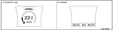
• Air conditioning system operation status is indicated on display in multi display unit. Indication of air conditioning system varies according to display mode of multi display unit. For changing procedure of display mode, refer to AV-99, "NISSAN DYNAMIC CONTROL SYSTEM : System Description".
- In CLIMATE mode: Operation status of air conditioning system (setting temperature, air flow, and “AUTO”*1) is indicated on display when air conditioning system is turned ON.
- In D-MODE: Operation status of air conditioning system (setting temperature, A/C switch, and “AUTO”*2) is indicated on lower portion of display when air conditioning system is turned ON.
NOTE
:
*1: AUTO is indicated when both air flow and air outlet are in automatic
control.
*2: Air Flow is indicated when air flow or air outlet is in manual control.
A/C Controller (Multi Display Unit) Operation procedure of air conditioning system varies depending on display mode of multi display unit. For changing procedure of display mode, refer to AV-99, "NISSAN DYNAMIC CONTROL SYSTEM : System Description".
• In CLIMATE mode: All operations of air conditioning system are possible.
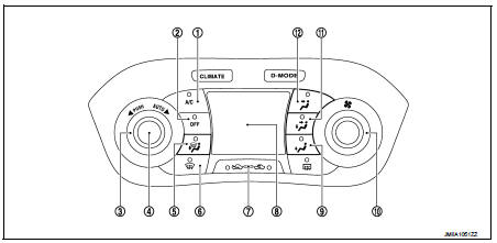
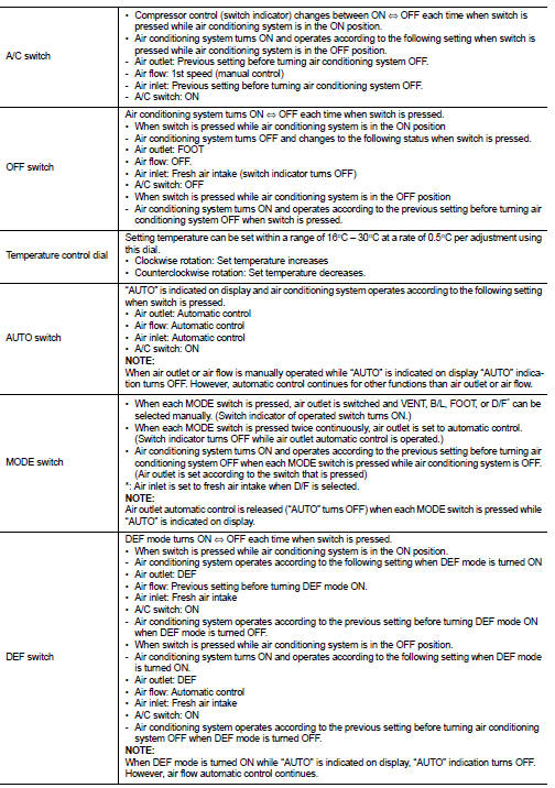
1. A/C switch
2. OFF switch
3. Temperature control dial
4. AUTO switch
5. MODE switch (D/F)
6. DEF switch
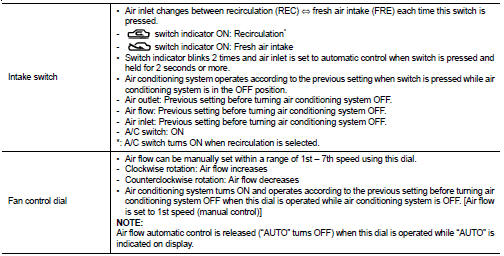
7. Intake switch
8. Display
9. MODE switch (FOOT)
10. Fan control dial
11. MODE switch (B/L)
12. MODE switch (VENT)
• In D-MODE: The following switches and dial cannot be operated.
- A/C switch
- OFF switch
- MODE switch
- Fan control dial
 System
Automatic air conditioning system : System Diagram
Automatic air conditioning system : System Description
DESCRIPTION
• Automatic air conditioning system is controlled by each function of A/C
a ...
 Diagnosis system (A/C auto AMP.)
Description
Air conditioning system performs self-diagnosis, operation check, function
diagnosis, and various settings
using diagnosis function of each control unit.
CONSULT-III Function
CONSU ...
Other materials:
Engine control system
Symptom Table
SYSTEM — BASIC ENGINE CONTROL SYSTEM
1 - 6: The numbers refer to the order of inspection.
(continued on next page)
SYSTEM — ENGINE MECHANICAL & OTHER
1 - 6: The numbers refer to the order of inspection. ...
P0087, P0088, P0090 FRP control system
DTC Logic
DTC DETECTION LOGIC
NOTE:
• If DTC P0087 or P0090 is displayed with DTC P1197, first perform the trouble
diagnosis for DTC
P1197.
• DTC P0087 or P0090 may be displayed when running out of gas.
DTC CONFIRMATION PROCEDURE
1.PRECONDITIONING
If DTC Confirmation Procedure has been p ...
P1745 line pressure control
Description
The line pressure solenoid valve regulates the oil pump discharge pressure to
suit the driving condition in
response to a signal sent from the TCM.
DTC Logic
DTC DETECTION LOGIC
DTC CONFIRMATION PROCEDURE
NOTE:
If “DTC CONFIRMATION PROCEDURE” has been previously performed, alw ...
