Nissan Juke Service and Repair Manual : Oil pan
Exploded View
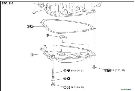
1. Transaxle assembly
2. Oil pan gasket
3. Magnet
4. Oil pan
5. Overflow tube
6. Drain plug gasket
7. Drain plug
8. Oil pan fitting bolt
 : Always replace after every
disassembly.
 : N·m (kg-m, ft-lb)
 : N·m (kg-m, it-lb)
Removal and Installation
REMOVAL
1. Remove the drain plug and overflow tube, and then drain the CVT fluid.
CAUTION:
Use caution when looking into the drain hole as there is the risk of fluid
entering the eye.
2. Remove the drain plug gasket from the drain plug.
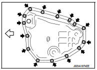
3. Remove the oil pan mounting bolts (
 ), and then remove the oil
pan and oil pan gasket.
 :Vehicle front
4. Remove the magnets from the oil pan.
INSTALLATION
Note the following, and install in the reverse order of removal.
CAUTION:
• Never reuse oil pan gasket and drain plug gasket.
• When installing the oil pan mounting bolts, be sure to use new bolts.
• Completely remove all moisture, oil and old gasket, etc. from the oil pan gasket mounting surface of transaxle case and oil pan.
• When installing the overflow tube, be sure to tighten to the specified torque. If it is not tightened to the specified torque, the tube may be damaged.
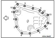
• When the oil pan is installed, tighten bolts in the order shown in the figure after temporarily tightening the oil pan mounting bolt.
:Vehicle front
Inspection and Adjustment
INSPECTION AFTER REMOVAL
Check oil pan for foreign material.
• If a large amount of worn material is found, clutch plate may be worn.
• If iron powder is found, bearings, gears, or clutch plates may be worn.
• If aluminum powder is found, bushing may be worn, or chips or burrs of aluminum casting parts may enter.
Check points where wear is found in all cases.
INSPECTION AFTER INSTALLATION
Check for CVT fluid leakage. Refer to TM-480, "Inspection".
ADJUSTMENT AFTER INSTALLATION
Adjust the CVT fluid level. Refer to TM-379, "Adjustment".
 G sensor
Exploded View
1. Bracket
2. G sensor
: Vehicle front
: N·m (kg-m, ft-lb)
: N·m (kg-m, in-lb)
Removal and Installation
CAUTION:
• Never drop or strike G sensor, because it has little toleran ...
 Primary speed sensor
Exploded View
1. Transaxle assembly
2. O-ring
3. Primary speed sensor
: Always replace after every
disassembly.
: N m (kg-m, in-lb)
: Genuine NISSAN CVT Fluid NS-2
Removal and Installatio ...
Other materials:
P1612 chain of ECM-IMMU
DTC Logic
DTC DETECTION LOGIC
NOTE:
• If DTC P1612 is displayed with DTC U1000 (for BCM), first perform the trouble
diagnosis for DTC U1000.
Refer to BCS-83, "DTC Logic".
• If DTC P1612 is displayed with DTC U1010 (for BCM), first perform the trouble
diagnosis for DTC U1010.
...
Brake warning lamp
Component Function Check
1.CHECK BRAKE WARNING LAMP FUNCTION (1)
Check that brake warning lamp in combination meter turns ON for approx. 1
second after ignition switch is
turned ON.
CAUTION:
Never start engine.
Is the inspection result normal?
YES >> GO TO 2.
NO >> Proceed ...
Spiral cable
Exploded View
1. Steering column upper cover
2. Steering column assembly
3. Steering column lower cover
4. Side lid LH
5. TORX bolt
6. Driver air bag module
7. TORX bolt
8. Side lid RH
9. Steering wheel
10. Spiral cable
11. Steering angle sensor
12. Combination switch
13. Stee ...
