Nissan Juke Service and Repair Manual : Map lamp
Exploded View
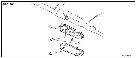
1. Map lamp bulb housing
2. Bulb
3. Lens
 : Pawl
Removal and Installation
CAUTION:
Disconnect the battery negative terminal or the fuse.
REMOVAL
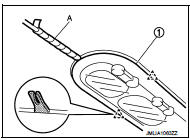
1. Remove the lens (1).
• Insert a remover tool (A) into the gap between the lens.
• Disengage the lens fixing pawls, and then remove the lens.
CAUTION:
Use a remover tool wrapped in tape.
2. Press pawl in the direction shown by the arrow in the figure using a remover tool (A), and then pull the map lamp housing (1) in the direction shown by the arrow in the figure.
CAUTION:
Use a remover tool wrapped in tape.
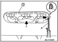
3. Disconnect map lamp harness connector, and then remove map lamp housing.
INSTALLATION
Install in the reverse order of removal.
Replacement
CAUTION:
• Disconnect battery negative terminal or the fuse.
• Never touch glass of bulb directly by hand. Keep grease and other oily matters away from it.
• Never touch bulb by hand while it is lit or right after being turned off.
• Never leave bulb out of lamp reflector for a long time because dust, moisture smoke, etc. may affect the performance of lamp. When replacing bulb, be sure to replace it with new one.
MAP LAMP BULB
1. Remove the lens (1).
• Insert a remover tool (A) into the gap between the lens.
• Disengage the lens fixing pawls, and then remove the lens.
 : Pawl
CAUTION:
Use a remover tool wrapped in tape.
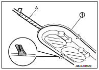
2. Remove the bulb.

 Luggage room lamp
Exploded View
1. Bulb housing
2. Bulb
3. Lens
: Pawl
Removal and Installation
CAUTION:
Disconnect the battery cable from negative terminal or remove the fuse.
REMOVAL
1. Insert a remover ...
Other materials:
Precaution
Precaution for Supplemental Restraint System (SRS) "AIR BAG" and "SEAT
BELT
PRE-TENSIONER"
The Supplemental Restraint System such as “AIR BAG” and “SEAT BELT PRE-TENSIONER”,
used along
with a front seat belt, helps to reduce the risk or severity of injury to the
driver a ...
Starter motor drive control
Starter motor drive control : System Diagram
Starter motor drive control : System
DescriptionINPUT/OUTPUT SIGNAL CHART
INPUT/OUTPUT SIGNAL CHART
*: With Intelligent Key system
SYSTEM DESCRIPTION
When rapid deceleration occurs during engine runs or idle speed decreases due
to heavy load c ...
Engine stand setting
NOTE:
Explained here is how to disassemble with engine stand supporting transaxle
surface. When using different
type of engine stand, note with difference in steps and etc.
1. Remove the engine and the transaxle assembly from the vehicle, and separate
the transaxle from the
engine. Refer t ...
