Nissan Juke Service and Repair Manual : Mainshaft and gear
Exploded View
1. Mainshaft front bearing outer
race
2. Mainshaft front bearing inner race
3. Mainshaft
4. 1st main gear
5. 1st inner baulk ring
6. 1st synchronizer cone
7. 1st outer baulk ring
8. 1st-2nd coupling sleeve
9. Insert key
10. 1st-2nd synchronizer hub
11. 2nd outer baulk ring
12. 2nd synchronizer cone
13. 2nd inner baulk ring
14. 2nd main gear
15. Bushing
16. 3rd main gear
17. Mainshaft adjusting shim
18. 4th main gear
19. 5th main gear
20. 6th main gear
21. Mainshaft rear bearing inner race
22. Mainshaft rear bearing outer race
23. Snap ring
24. Mainshaft rear bearing adjusting
shim
 : Apply gear oil.
 : Replace the parts as a set.
 : Select with proper thickness.
 : Always replace after every
disassembl
Disassembly
CAUTION:
• Fix mainshaft in a vise with back plate, and then remove gears and snap
rings.
• For removal of snap ring, set snap ring pliers and flat pliers at both sides of snap ring. While expanding snap ring with snap ring pliers, move snap ring with flat pliers.
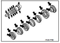
• Disassemble gear components putting direction marks on the parts that never affect any functions.
1. Remove snap ring (1).
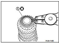
2. Remove 6th main gear (1) and mainshaft rear bearing inner race (2), as per the following procedure.
a. Set a puller [Commercial service tool] to 6th main gear.
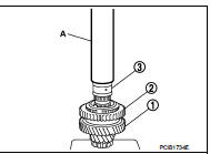
b. Remove mainshaft rear bearing inner race and 6th main gear, using the drift (A) [SST: ST33052000].
3. Remove 4th main gear (1) and 5th main gear (2), as per the following procedure.
a. Set a puller [Commercial service tool] to 4th main gear.
b. Remove 5th main gear and 4th main gear, using the drift (A) [SST: ST33052000].
4. Remove mainshaft adjusting shim.
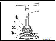
5. Remove 1st main gear (1), 1st-2nd synchronizer hub assembly (2), 2nd main gear (3), and 3rd main gear (4), as per the following procedure.
a. Set a puller [Commercial service tool] to 1st main gear.
b. Remove 3rd main gear, busing, 2nd main gear, 2nd inner baulk ring, 2nd synchronizer cone, 2nd outer baulk ring, 1st-2nd synchronizer hub assembly, 1st outer baulk ring, 1st synchronizer cone, 1st inner baulk ring, and 1st main gear, using the drift (A) [SST: ST33052000].
c. Remove insert keys and 1st-2nd coupling sleeve from 1st-2nd synchronizer hub.
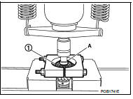
6. Remove mainshaft front bearing inner race (1), as per the following procedure.
a. Set a puller [Commercial service tool] to mainshaft front bearing inner race.
b. Remove mainshaft front bearing inner race, using the drift (A) [SST: ST33052000].
Assembly
CAUTION:
• Select mainshaft rear bearing adjusting shim, as per the following procedure
when replacing mainshaft
adjusting shim, 6th main gear, 5th main gear, or 4th main gear.
- Replace mainshaft adjusting shim.
• If new mainshaft adjusting shim is thinner than previous one, offset the thickness difference by selecting thicker mainshaft rear bearing adjusting shim.
• If new mainshaft adjusting shim is thicker than previous one, offset the thickness difference by selecting thinner mainshaft rear bearing adjusting shim.
- Replace 6th main gear, 5th main gear, or 4th main gear.
• Measure the thickness of the main gear used before and the new main gear • Increase the thickness of the mainshaft rear bearing adjusting shim, if the difference is smaller than 0.025 mm (0.0010 in).
• Replace transaxle assembly when replacing mainshaft.
• For installation of snap ring, set snap ring pliers and flat pliers at both sides of snap ring. While expanding snap ring with snap ring pliers, move snap ring with flat pliers.
1. Install mainshaft front bearing inner race (1), using the drift (A) [SST: ST36720030].
CAUTION:
Replace mainshaft front bearing outer race and mainshaft
front bearing inner race as a set
.
2. Apply gear oil to 1st inner baulk ring, 1st synchronizer cone, 1st outer baulk ring, 2nd inner baulk ring, 2nd synchronizer cone, and 2nd outer baulk ring.
CAUTION:
• Replace 1st inner baulk ring, 1st synchronizer cone, and
1st outer baulk ring as a set.
• Replace 2nd inner baulk ring, 2nd synchronizer cone, and 2nd outer baulk ring as a set.
3. Install insert keys and 1st-2nd coupling sleeve to 1st-2nd synchronizer hub.
CAUTION:
Replace 1st-2nd synchronizer hub and 1st-2nd coupling sleeve as a set.
4. Install 1st main gear (1), 1st inner baulk ring, 1st synchronizer cone, 1st outer baulk ring, 1st-2nd synchronizer hub assembly (2), 2nd inner baulk ring, 2nd synchronizer cone, and 2nd outer baulk ring.
5. Install bushing (3), using the drift (A) [SST: KV32102700].
6. Install 3rd main gear (1) and 2nd main gear (2), using the drift (A) [SST: KV32102700].
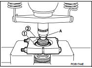
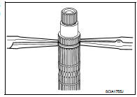
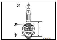
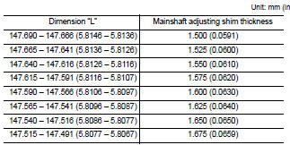
7. Measure dimension “L” as shown in the figure. Select mainshaft adjusting shim (1) according to the following list, and then install it to mainshaft.
2 : Mainshaft
3 : 3rd main gea
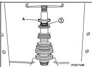
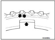
![8. Install 4th main gear (1), using the drift (A) [SST: KV32102700].](images/books/335/26/index254.jpg)
8. Install 4th main gear (1), using the drift (A) [SST: KV32102700].
![9. Install 5th main gear (1), using the drift (A) [SST: KV32102700].](images/books/335/26/index255.gif)
9. Install 5th main gear (1), using the drift (A) [SST: KV32102700].
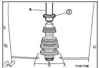
![10. Install 6th main gear (1), using the drift (A) [SST: KV32102700].](images/books/335/26/index256.jpg)
10. Install 6th main gear (1), using the drift (A) [SST: KV32102700].
11. Install mainshaft rear bearing inner race (1), using the drift (A) [SST: ST30901000].
CAUTION:
Replace mainshaft rear bearing inner race and mainshaft
rear bearing outer race as a set.
12. Install snap ring.
CAUTION:
Never reuse snap ring.
Inspection
INSPECTION AFTER DISASSEMBLY
Mainshaft and Gear Check the following items and replace if necessary.
• Damage, peeling, bend, uneven wear, and distortion of shaft.
• Excessive wear, damage, and peeling of gear.
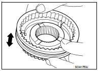
Synchronizer Hub and Coupling Sleeve Check the following items and replace if necessary.
• Breakage, damage, and unusual wear on contact surface of coupling sleeve, synchronizer hub, and insert key.
• Coupling sleeve and synchronizer hub move smoothly.
Baulk Ring
Check contact surface of baulk ring cam and insert key for excessive
wear, uneven wear, bend, and damage. Replace if necessary.
Bearing
Check bearing for damage and unsmooth rotation. Replace if necessary.
CAUTION:
• Replace mainshaft front bearing outer race and mainshaft
front bearing inner race as a set.
• Replace mainshaft rear bearing inner race and mainshaft rear bearing outer race as a set.
 Input shaft and gear
Exploded View
1. Input shaft front bearing
2. Input shaft
3. 3rd input gear
4. Spacer
5. Snap ring
6. 3rd baulk ring
7. 3rd-4th coupling sleeve
8. 3rd-4th synchronizer hub
9. Insert k ...
 Reverse idler shaft and gear
Exploded View
1. Reverse output gear
2. Snap ring
3. Reverse baulk ring
4. Return spring
5. Needle bearing
6. Seal washer
7. Reverse idler shaft
8. Spacer
9. Reverse input gear
10. L ...
Other materials:
Magnet clutch
Component Function Check
1.CHECK MAGNET CLUTCH OPERATION
Perform auto active test of IPDM E/R. Refer to PCS-12, "Diagnosis
Description" (with Intelligent Key) or PCS-
43, "Diagnosis Description" (without Intelligent Key).
Does it operate normally?
YES >> INSPECTION ...
Component parts
Component Parts Location
1. BCM
Refer to BCS-6, "BODY CONTROL
SYSTEM : Component Parts Location"
(with Intelligent Key) or BCS-96,
"BODY CONTROL SYSTEM : Component
Parts Location" (without Intelligent
Key)
2. Power window main switch
3. Front power window motor (drive ...
P0657 ECM relay
DTC Logic
DTC DETECTION LOGIC
NOTE:
When IPDM E/R DTC is indicated with DTC P0657, IPDM E/R DTC must be checked
first.
Diagnosis Procedure
1.CHECK GROUND CONNECTION
1. Turn ignition switch OFF.
2. Check ground connection E38. Refer to Ground Inspection in GI-44, "Circuit
Inspection ...
