Nissan Juke Service and Repair Manual : Main power supply and ground circuit
Diagnosis Procedure
1.CHECK TCM POWER CIRCUIT 1
1. Turn the ignition switch OFF.
2. Disconnect the TCM connector.
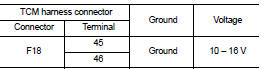
3. Check the voltage between the TCM harness connector terminals and ground.
Is the inspection result normal? YES >> GO TO 2.
NO >> GO TO 4.
2.CHECK TCM POWER CIRCUIT 2
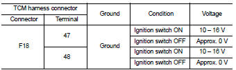
Check the voltage between the TCM harness connector terminals and ground.
Is the inspection result normal? YES >> GO TO 3.
NO >> GO TO 5.
3.CHECK TCM GROUND CIRCUIT
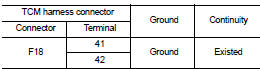
Check the continuity between TCM harness connector terminals and ground.
Is the inspection result normal? YES >> Check intermittent incident. Refer to GI-42, "Intermittent Incident".
NO >> Repair or replace the malfunctioning parts.
4.DETECT MALFUNCTION ITEMS (PART 1)
Check the following items: • Open or short circuit of the harness between battery positive terminal and TCM connectors terminals 45 and 46. Refer to PG-10, "Wiring Diagram - BATTERY POWER SUPPLY -".
• 10A fuse (No.33, fuse and fusible link block). Refer to PG-23, "Fuse and Fusible Link Arrangement".
• 10A fuse (No.36, fuse and fusible link block). Refer to PG-23, "Fuse and Fusible Link Arrangement".
Is the inspection result normal? YES >> Check intermittent incident. Refer to GI-42, "Intermittent Incident".
NO >> Repair or replace the malfunctioning parts.
5.CHECK CIRCUIT BETWEEN IPDM E/R AND TCM (PART 1)
1. Turn ignition switch OFF.
2. Disconnect the IPDM E/R connector.
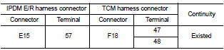
3. Check continuity between IPDM E/R harness connector terminal and TCM harness connector terminals.
Is the check result normal? YES >> GO TO 6.
NO >> Repair or replace the malfunctioning parts.
6.CHECK CIRCUIT BETWEEN IPDM E/R AND TCM (PART 2)
Check continuity between IPDM E/R harness connector terminal and ground.
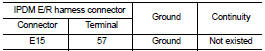
Is the check result normal? YES >> GO TO 7.
NO >> Repair or replace the malfunctioning parts.
7.DETECTION OF MALFUNCTION ITEMS (PART 2)
Check the following items: • Harness open circuit or short circuit between the ignition switch and IPDM E/R. Refer to PG-15, "Wiring Diagram - IGNITION POWER SUPPLY -".
• 10A fuse (No.55, IPDM E/R). Refer to PG-25, "Fuse, Connector and Terminal Arrangement".
• IPDM E/R
Is the check result normal? YES >> Check intermittent incident. Refer to GI-42, "Intermittent Incident".
NO >> Repair or replace the malfunctioning parts.
 P2765 clutch B speed sensor
DTC Logic
DTC DETECTION LOGIC
DTC CONFIRMATION PROCEDURE
CAUTION:
Be careful of the driving speed.
1.PREPARATION BEFORE WORK
If another "DTC CONFIRMATION PROCEDURE" occurs just befor ...
 S mode switch
Component Function Check
1.CHECK S MODE INDICATOR FUNCTION
Check S mode indicator turns ON for approx. 2 seconds when ignition switch
turns ON.
Is the inspection results normal?
YES >> G ...
Other materials:
Additional service when replacing
ECM
Description
When replacing ECM, this procedure must be performed.
Work Procedure
1.PERFORM INITIALIZATION OF NATS SYSTEM AND REGISTRATION OF ALL NATS
IGNITION KEY IDS
Refer to SEC-50, "ECM : Work Procedure".
>> GO TO 2.
2.PERFORM ACCELERATOR PEDAL RELEASED POSITION LEARNIN ...
Inside mirror
Adjust the angle of the inside mirror to the desired position.
The night position1 will reduce glare from the headlights of vehicles behind
you at night.
Use the day position2 when driving in daylight hours.
WARNING
Use the night position only when necessary, because it reduces rear view c ...
Engine control system
Symptom Table
SYSTEM — BASIC ENGINE CONTROL SYSTEM
1 - 6: The numbers refer to the order of inspection.
(continued on next page)
SYSTEM — ENGINE MECHANICAL & OTHER
1 - 6: The numbers refer to the order of inspection. ...
