Nissan Juke Service and Repair Manual : Magnet clutch
Component Function Check
1.CHECK MAGNET CLUTCH OPERATION
Perform auto active test of IPDM E/R. Refer to PCS-12, "Diagnosis Description" (with Intelligent Key) or PCS- 43, "Diagnosis Description" (without Intelligent Key).
Does it operate normally? YES >> INSPECTION END
NO >> Refer to HAC-83, "Diagnosis Procedure".
Diagnosis Procedure
1.CHECK FUSE
1. Turn ignition switch OFF.
2. Check 10A fuse (No. 49, located in IPDM E/R).
NOTE
:
Refer to PG-25, "Fuse, Connector and Terminal Arrangement".
Is the inspection result normal? YES >> GO TO 2.
NO >> Replace the blown fuse after repairing the affected circuit if a fuse is blown.
2.CHECK MAGNET CLUTCH
1. Disconnect compressor connector.
2. Directly apply battery voltage to the magnet clutch. Check for operation visually and by sound.
Does it operate normally? YES >> GO TO 3.
NO >> Replace magnet clutch. Refer to HA-88, "MAGNET CLUTCH : Removal and Installation of Compressor Clutch".
3.CHECK MAGNET CLUTCH POWER SUPPLY CIRCUIT FOR OPEN
1. Disconnect IPDM E/R connector.
2. Check continuity between IPDM E/R harness connector and compressor harness connector.
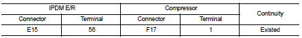
Is the inspection result normal? YES >> Replace IPDM E/R. Refer to PCS-34, "Removal and Installation" (with Intelligent Key) or PCS-63, "Removal and Installation" (without Intelligent Key).
NO >> Repair harness or connector.
 Blower motor
Diagnosis Procedure
1.CHECK FUSE
1. Turn ignition switch OFF.
2. Check following fuses.
- 10A fuse [No. 15, located in fuse block (J/B)]
- 15A fuses [Nos. 14 and 16, located in fuse block (J/B) ...

Other materials:
U1000 can comm circuit
Description
CAN (Controller Area Network) is a serial communication system for real time
application. It is an on-vehicle
multiplex communication system with high data communication speed and excellent
error detectability. Many
electronic control units are equipped onto vehicles, and each con ...
Parking brake control
Exploded View
2WD
1. Parking brake lever assembly
2. Adjusting nut
3. Parking brake switch
4. Front cable
5. Rear cable (LH)
6. Rear cable (RH)
: Apply multi-purpose grease.
: N·m (kg-m, ft-lb)
: N·m (kg-m, in-lb)
: Always replace after every
disassembly.
4WD
1. Parking brake ...
Removal and Installation
REMOVAL
• Disconnect each joint and mounting.
• Remove heated oxygen sensor 2 with following procedure:
- Using heated oxygen sensor wrench [SST: KV10114400] (A),
removal heated oxygen sensor 2 (1).
CAUTION:
Be careful not to damage heated oxygen sensor 2.
INSTALLATION
Note the following ...
