Nissan Juke Service and Repair Manual : LAN System can system (type 7)
DTC/CIRCUIT DIAGNOSIS
Main line between IPDM-E and DLC circuit
Diagnosis Procedure
1.CHECK CONNECTOR
1. Turn the ignition switch OFF.
2. Disconnect the battery cable from the negative terminal.
3. Check the following terminals and connectors for damage, bend and loose connection (connector side and harness side).
- Harness connector E105 - Harness connector M77
Is the inspection result normal? YES >> GO TO 2.
NO >> Repair the terminal and connector.
2.CHECK HARNESS CONTINUITY (OPEN CIRCUIT)
1. Disconnect the following harness connectors.
- IPDM E/R
- Harness connectors E105 and M77
2. Check the continuity between the IPDM E/R harness connector and the harness
connector.
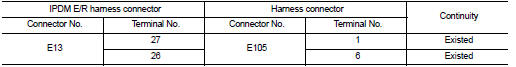
Is the inspection result normal? YES >> GO TO 3.
NO >> Repair the main line between the IPDM E/R and the harness connector E105.
3.CHECK HARNESS CONTINUITY (OPEN CIRCUIT)
Check the continuity between the harness connector and the data link connector.
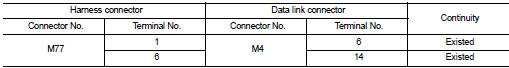
Is the inspection result normal? YES (Present error)>>Check CAN system type decision again.
YES (Past error)>>Error was detected in the main line between the IPDM E/R and the data link connector.
NO >> Repair the main line between the harness connector M77 and the data link connector.
Main line between DLC and MDU circuit
Diagnosis Procedure
1.CHECK HARNESS CONTINUITY (OPEN CIRCUIT)
1. Turn the ignition switch OFF.
2. Disconnect the battery cable from the negative terminal.
3. Disconnect the following harness connectors.
- ECM
- Multi display unit
4. Check the continuity between the data link connector and the multi display
unit harness connector.
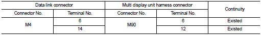
Is the inspection result normal? YES (Present error)>>Check CAN system type decision again.
YES (Past error)>>Error was detected in the main line between the the data link connector and the multi display unit.
NO >> Repair the main line between the data link connector and the multi display unit.
 LAN System can system (type 6)
DTC/CIRCUIT DIAGNOSIS
Main line between IPDM-E and DLC circuit
Diagnosis Procedure
1.CHECK CONNECTOR
1. Turn the ignition switch OFF.
2. Disconnect the battery cable from the negative terminal.
...
 ECM branch line circuit
Diagnosis Procedure
1.CHECK CONNECTOR
1. Turn the ignition switch OFF.
2. Disconnect the battery cable from the negative terminal.
3. Check the terminals and connectors of the ECM for damage, bend ...
Other materials:
Steering switch signal B circuit
Description
Transmits the steering switch signal to NAVI control unit.
Diagnosis Procedure
1.CHECK STEERING SWITCH SIGNAL B CIRCUIT
1. Disconnect NAVI control unit connector and spiral cable connector.
2. Check continuity between NAVI control unit harness connector and spiral cable
harness co ...
FM-AM-SAT radio with Compact Disc (CD) player (Type A)
1. MUTE button
2. DISP (display)/TEXT button
3. FM·AM radio band select button
4. CD PLAY button
5. Radio station preset buttons
6. iPod® button
7. AUX (auxiliary)/SAT band select button
8. Audio display
9. CLOCK button
10. CD EJECT button
11. iPod® MENU button
12. SEEK/TRACK button
13 ...
Front wiper motor lo circuit
Component Function Check
1.CHECK FRONT WIPER LO OPERATION
CONSULT-III ACTIVE TEST
1. Select “FRONT WIPER” of IPDM E/R active test item.
2. With operating the test item, check front wiper operation.
Lo : Front wiper (LO) operation
Off : Stop the front wiper.
Is front wiper (LO) operation norma ...
