Nissan Juke Service and Repair Manual : Intelligent key warning buzzer
Component Function Check
1.CHECK FUNCTION
1. Select “INTELLIGENT KEY” of “BCM” using CONSULT-III.
2. Select “OUTSIDE BUZZER” in “ACTIVE TEST” mode.
3. Check that the function operates normally according to the following conditions.
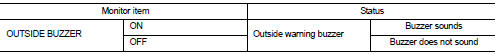
Is the inspection result normal? YES >> Intelligent Key warning buzzer is OK.
NO >> Refer to DLK-263, "Diagnosis Procedure".
Diagnosis Procedure
1.CHECK FUSE
1. Turn ignition switch OFF.
2. Check 10 A fuse, [No. 7, located in fuse block (J/B)].
Is the inspection result normal? YES >> GO TO 2.
NO >> Replace the blown fuse after repairing the affected circuit if a fuse is blown.
2.CHECK INTELLIGENT KEY WARNING BUZZER POWER SUPPLY CIRCUIT
1. Disconnect Intelligent Key warning buzzer connector.
2. Check voltage between Intelligent Key warning buzzer harness connector and ground.
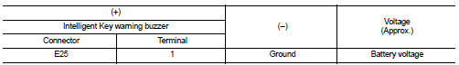
Is the inspection result normal? YES >> GO TO 3.
NO >> Repair or replace harness.
3.CHECK INTELLIGENT KEY WARNING BUZZER CIRCUIT
1. Disconnect BCM connector.
2. Check continuity between BCM harness connector and Intelligent Key warning buzzer harness connector.
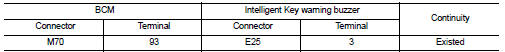
3. Check continuity between BCM harness connector and ground.
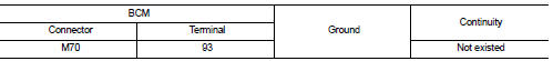
Is the inspection result normal? YES >> GO TO 4.
NO >> Repair or replace harness.
4.CHECK INTELLIGENT KEY WARNING BUZZER
Refer to DLK-264, "Component Inspection".
Is the inspection result normal? YES >> Replace BCM. Refer to BCS-93, "Removal and Installation".
NO >> Replace Intelligent Key warning buzzer.
Component Inspection
1.CHECK INTELLIGENT KEY WARNING BUZZER
1. Turn ignition switch OFF.
2. Disconnect Intelligent Key warning buzzer connector.
3. Connect battery power supply directly to Intelligent Key warning buzzer terminals and check the operation.
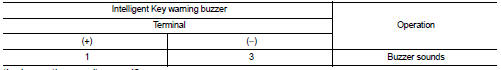
Is the inspection result normal? YES >> INSPECTION END
NO >> Replace Intelligent Key warning buzzer.
 Intelligent key
Component Function Check
1.CHECK FUNCTION
1. Select “INTELLIGENT KEY” of “BCM” using CONSULT-III.
2. Select “RKE OPE COUN1” in “DATA MONITOR” mode.
3. Check that the function operates normally acc ...
 Key warning lamp
Component Function Check
1.CHECK FUNCTION
1. Select “INTELLIGENT KEY” of “BCM” using CONSULT-III.
2. Select “INDICATOR” in “ACTIVE TEST” mode.
3. Check that the function operates normally accordin ...
Other materials:
P0641 sensor power supply
DTC Logic
DTC DETECTION LOGIC
Diagnosis Procedure
1.CHECK GROUND CONNECTION
1. Turn ignition switch OFF.
2. Check ground connection E38. Refer to Ground Inspection in GI-44, "Circuit
Inspection".
Is the inspection result normal?
YES >> GO TO 2.
NO >> Repair or r ...
Wiring diagram
Engine control system
For connector terminal arrangements, harness layouts, and alphabets in a
(option abbreviation; if not
described in wiring diagram), refer to GI-12, "Connector Information/Explanation
of Option Abbreviation".
...
Magnet clutch
Component Function Check
1.CHECK MAGNET CLUTCH OPERATION
Perform auto active test of IPDM E/R. Refer to PCS-12, "Diagnosis
Description" (with Intelligent Key) or PCS-
43, "Diagnosis Description" (without Intelligent Key).
Does it operate normally?
YES >> INSPECTION ...
