Nissan Juke Service and Repair Manual : Intake manifold
Exploded View
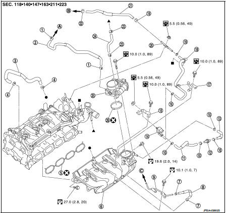
1. Clamp
2. Water hose
3. PCV hose
4. Clamp
5. Gasket
6. Intake manifold
7. Clamp
8. Vacuum hose
9. Vacuum gallery assembly
10. Clamp
11. EVAP hose
12. EVAP service port valve
13. EVAP hose
14.EVAP canister purge volume control
solenoid valve
15. Bracket
16. Clamp
17. Bracket
18. EVAP hose
19. Clamp
20. EVAP tube
21. EVAP hose
22. Clamp
23. Clamp
24. Water hose
25. Electric throttle control actuator
26. Gasket
A. To turbocharger B. To centralized under-floor piping C. To recirculation valve hose
 : N·m (kg-m, ft-lb)
 : N·m (kg-m, in-lb)
 : Always replace after every
disassembly
Removal and Installation
REMOVAL
1. Remove engine cover. Refer to EM-25, "Exploded View".
2. Pull out oil level gauge.
CAUTION:
Cover the oil level gauge guide openings to avoid entry of foreign materials.
3. Disconnect turbocharger boost sensor (with intake air temperature sensor 2) harness connector. Refer to EM-31, "Exploded View".
4. Remove air inlet tube assembly. Refer to EM-31, "Exploded View".
5. Disconnect water hoses from electric throttle control actuator as follows: • Attach plug to prevent engine coolant leakage when engine coolant is not drained. Refer to CO-11, "Draining".
CAUTION:
Perform this step when the engine is cold.
NOTE:
This step is not required when removing only intake manifold.
6. Disconnect electric throttle control actuator harness connector.
7. Remove electric throttle control actuator.
CAUTION
:
• Handle carefully to avoid any shock to electric throttle control
actuator.
• Never disassemble electric throttle control actuator.
8. Disconnect EVAP canister purge volume control solenoid valve harness connector, and them remove bracket with EVAP canister purge volume control solenoid valve.
9. Remove vacuum gallery.
10. Disconnect PCV hose (intake manifold side).
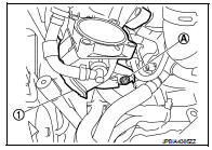
11. Remove intake manifold (1) with the following procedure.
• Loosen and remove intake manifold mounting bolt (A).
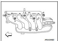
• Loosen mounting bolts in reverse order as shown in the figure.
 : Engine front
NOTE:
Disregard the numerical order No.6 in removal.
CAUTION:
Cover engine openings to avoid entry of foreign materials.
INSTALLATION
Note the following, and install in the reverse order of removal.
Intake Manifold
1. Check if gasket is not dropped from the installation groove of intake
manifold.
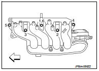
2. Install intake manifold with the following procedure:
a. Tighten in numerical order as shown in the figure.
: Engine front
NOTE:
• Tighten bolt the No.1 in two steps.
• The numerical order No.6 shows the second step.
3. Install in the reverse order of removal after this step.
Electric Throttle Control Actuator • Tighten bolts of electric throttle control actuator equally and diagonally in several steps.
• Perform “Throttle Valve Closed Position Learning” after repair when removing harness connector of the electric throttle control actuator. Refer to EC-135, "Work Procedure".
• Perform “Throttle Valve Closed Position Learning” and “Idle Air Volume Learning” after repair when replacing electric throttle control actuator. Refer to EC-135, "Work Procedure" and EC-136, "Work Procedure".
 Air cleaner and air duct
Exploded View
1. Mass air flow sensor
2. Gasket
3. Clamp
4. Air duct (suction side)
5. Clamp
6. Air cleaner cover assembly
7. Mounting rubber
8. Air cleaner filter
9. Air cleaner body ...
 Charge air cooler
Exploded View
1. Air inlet tube assembly
2. Air inlet tube bracket
3. Clamp
4. Air inlet hose
5. Gasket
6. Turbocharger
7. Mounting rubber
8. Charge air cooler
9. Air inlet tube assem ...
Other materials:
Engine maintenance (K9K)
Drive belt
DRIVE BELT : Checking Drive Belts
WARNING:
Be sure to perform when the engine is stopped.
1. Inspect belts for cracks, fraying, wear and oil. If necessary,
replace.
2. Evaluate manually if the belt is enough tensioned (tension cannot
be measured by way of frequency meter).
CAU ...
B2628 outside antenna
DTC Logic
DTC DETECTION LOGIC
DTC CONFIRMATION PROCEDURE
1.PERFORM DTC CONFIRMATION PROCEDURE
1. Disconnect outside key antenna (rear bumper) connector.
2. Perform “INTELLIGENT KEY” Self Diagnostic Result.
Is outside key antenna DTC detected?
YES >> Refer to DLK-65, "Diagnosis ...
U1010 control unit (can)
Description
CAN (Controller Area Network) is a serial communication line for real time
application. It is an on-vehicle multiplex
communication line with high data communication speed and excellent error
detection ability. Many electronic
control units are equipped onto a vehicle, and each co ...
