Nissan Juke Service and Repair Manual : Inspection
INSPECTION AFTER REMOVAL
Appearance
Check the propeller shaft for bend and damage. If damage is detected, replace
propeller shaft assembly.
Propeller Shaft Runout
Check propeller shaft runout at measuring points with a dial indicator.
If runout exceeds specifications, replace propeller shaft assembly.
Propeller shaft runout : Refer to DLN-125, "Propeller Shaft Runout".
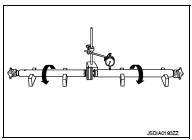
• Propeller shaft runout measuring point (Point “
”)
 : Front
Dimension A: 542 mm (21.34 in) B: 516.5 mm (20.33 in)
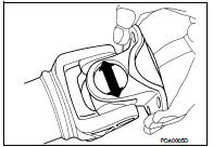
Journal Axial Play
As shown in the figure, while fixing yoke on one side, check axial
play of joint. If it is outside the standard, replace propeller shaft
assembly.
Journal axial play : Refer to DLN-125, "Journal Axial Play".
CAUTION:
Never disassemble joints.
Center Bearing
Check center bearing for noise and damage. If noise or damage is detected,
replace propeller shaft assembly.
CAUTION:
Never disassemble center bearing.
INSPECTION AFTER INSTALLATION
After assembly, perform a driving test to check propeller shaft vibration. If vibration occurred, separate propeller shaft from final drive or transfer. Reinstall companion flange by changing the phase between companion flange and propeller shaft by the one bolt hole at a time. Then perform driving test and check propeller shaft vibration again at each point.
 Removal and Installation
REMOVAL
1. Shift the transaxle to the neutral position, and then release the parking
brake.
2. Put matching marks on propeller shaft flange yoke and final drive companion
flanges.
CAUTION:
F ...

Other materials:
System (intelligent key system)
Intelligent key system
INTELLIGENT KEY SYSTEM : System Diagram
INTELLIGENT KEY SYSTEM : System Description
• The Intelligent Key system is a system that makes it possible to lock and
unlock the door locks (door lock/
unlock function) by carrying the Intelligent Key, which operates based on t ...
Engine control system symptoms
Symptom Table
SYSTEM — BASIC ENGINE CONTROL SYSTEM
1 - 6: The numbers refer to the order of inspection.
(continued on next table)
SYSTEM — ENGINE MECHANICAL & OTHER
1 - 6: The numbers refer to the order of inspection ...
P0102, P0103 MAF SENSOR
DTC Logic
DTC DETECTION LOGIC
DTC CONFIRMATION PROCEDURE
1.PRECONDITIONING
If DTC Confirmation Procedure has been previously conducted, always turn
ignition switch OFF and wait at
least 10 seconds before conducting the next test.
Which DTC is detected?
P0102 >> GO TO 2.
P0103 & ...
