Nissan Juke Service and Repair Manual : Inside key antenna
Instrument center
INSTRUMENT CENTER : Removal and Installation
REMOVAL
1. Remove the multi display unit. Refer to AV-125, "Removal and Installation".
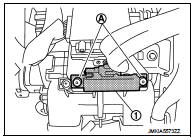
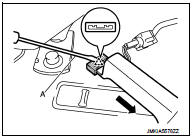
2. Remove the inside key antenna (instrument center) (1) mounting clip (A), and then remove inside key antenna (instrument center).
CAUTION:
Be careful not to drop mounting clip (A) into instrument
panel.
INSTALLATION
Install in the reverse order of removal.
Console
CONSOLE : Removal and Installation
REMOVAL
1. Remove the center console assembly. Refer to IP-23, "Removal and Installation".
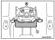
2. Remove the inside key antenna (console) (1) mounting clip (A), and then remove inside key antenna (console).
INSTALLATION
Install in the reverse order of remova
Luggage room
LUGGAGE ROOM : Exploded View
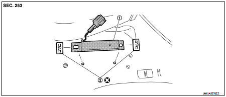
1. Inside key antenna (luggage room) 2. Clip
 : Do not reuse
LUGGAGE ROOM : Removal and Installation
REMOVAL
1. Remove the luggage floor finisher. Refer to INT-29, "Exploded View".
2. Remove the inside key antenna (luggage room) (1) mounting clip RH (A).
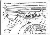
3. Disengage inside key antenna (luggage room) fixing clip using a flat-bladed screwdriver (A), and then pull out forward the inside key antenna (luggage room).
INSTALLATION
Install in the reverse order of removal.
CAUTION:
Visually check the clips for deformation and damage during installation.
Replace with new ones if necessary.
 Door switch
Exploded View
1. Door switch
2. TORX bolt
Removal and Installation
REMOVAL
Remove the TORX bolt (A), and then remove door switch (1).
INSTALLATION
Install in the reverse order of removal. ...
 Outside key antennA
Driver side
DRIVER SIDE : Removal and Installation
REMOVAL
Remove the driver side outside handle. Refer to DLK-339, "OUTSIDE HANDLE :
Removal and Installation".
INSTALLATION
Install ...
Other materials:
System (intelligent key system)
Intelligent key system : System Diagram
Intelligent key system : System Description
• The Intelligent Key system is a system that makes it possible to lock and
unlock the door locks (door lock/
unlock function) by carrying the Intelligent Key, which operates based on the
results of electron ...
Water outlet
Exploded View
1. Engine coolant temperature sensor
2. O-ring
3. Lock plate
4. Gasket
5. Water outlet and thermostat assembly
6. Air relief plug
7. Clamp
8. Water hose
9. Water pipe
A. To radiator hose upper
B. To EGR cooler hose
C. To heater hose
: N·m (kg-m, ft-lb)
: Always ...
P1551, P1552 battery current sensor
DTC Logic
DTC DETECTION LOGIC
DTC CONFIRMATION PROCEDURE
1.PRECONDITIONING
If DTC Confirmation Procedure has been previously conducted, always perform
the following before conducting
the next test.
1. Turn ignition switch OFF and wait at least 10 seconds.
2. Turn ignition switch ON.
3. ...
