Nissan Juke Service and Repair Manual : Ignition coil, spark plug and rocker cover
Exploded View
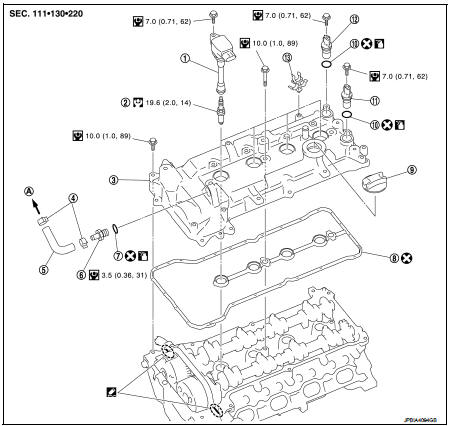
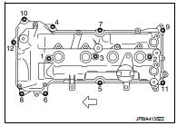
1. Ignition coil
2. Spark plug
3. Rocker cover
4. Hose cramp
5. PCV hose
6. PCV valve
7. O-ring
8. Gasket
9. Oil filler cap
10. O-ring
11. Camshaft position sensor (INT)
12. Camshaft position sensor (EXH)
13. Cramp
A. To intake manifold
 : Always replace after every
disassembly.
 : N·m (kg-m, in-lb)
 : N·m (kg-m, ft-lb)
 : Sealing point
 : Should be lubricated with oil.
Removal and Installation
REMOVAL
1. Remove intake manifold. Refer to EM-163, "Exploded View".
2. Remove ignition coil.
CAUTION:
• Never drop or shock ignition coil.
• Never disassemble ignition coil.
. Remove fuel tube protector. Refer to EM-173, "Exploded View".
4. Remove PCV hose from rocker cover.
5. Remove PCV valve, if necessary.
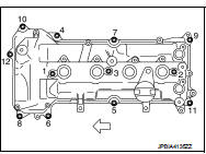
6. Remove rocker cover.
• Loosen bolts in reverse order as shown in the figure.
 : Engine front
7. Remove rocker cover gasket from rocker cover.
8. Use scraper to remove all traces of liquid gasket from cylinder head and front cover.
CAUTION:
Never scratch or damage the mating surface when cleaning off old liquid gasket.
INSTALLATION
1. Rocker cover with the following procedure: a. Press gasket onto the bosses for the rocker cover bolt holes as shown in the figure to prevent the rocker cover from dropping off.
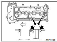
b. Apply liquid gasket to the position as shown in the figure.
1 : Cylinder head
2 : Front cover
a : φ2.5 - 3.5 mm
Use Genuine Liquid Gasket or equivalent.
c. Install rocker cover to cylinder head.
CAUTION:
Check the gasket is not dropped.
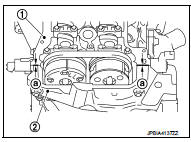
• Tighten bolts in two steps separately in numerical order as shown in the figure.
: Engine front
2. Install PCV valve.
• Insert PCV valve until the flange of PCV valve contact the grommet absolutely.
3. Install in the reverse order of removal, for the rest of parts.
 Fuel injector and fuel tube
Exploded View
1. Stud bolt
2. O-ring (green)
3. Fuel injector (front)
4. Clip
5. Fuel injector (rear)
6. O-ring (black)
7. Fuel tube protector
8. Fuel tube
9. Fuel feed hose
10. Qui ...
 Timing chain
Exploded View
1. Timing chain slack guide
2. Timing chain tensioner
3. Camshaft sprocket (EXH)
4. Camshaft sprocket (INT)
5. Plug 6. Front oil seal
7. Crankshaft pulley
8. Crankshaft pull ...
Other materials:
Push-button ignition switch
Removal and Installation
REMOVAL
1. Remove the NATS antenna amp. Refer to SEC-167, "Removal and
Installation".
2. Remove the push-button ignition switch.
1. Disengage the push-button ignition switch fixing pawls
using minus driver etc.
2. Press the push-button ignition switch to ...
P0697 sensor power supply
DTC Logic
DTC DETECTION LOGIC
Diagnosis Procedure
1.CHECK GROUND CONNECTION
1. Turn ignition switch OFF and wait at least 4 minutes.
2. Check ground connection E38. Refer to Ground Inspection in GI-44, "Circuit
Inspection".
Is the inspection result normal?
YES >> GO TO 2 ...
Rear power window switch
Component Function Check
1. CHECK REAR POWER WINDOW SWITCH FUNCTION
Check rear power window motor operation with rear power window switch.
Is the inspection result normal?
YES >> INSPECTION END
NO >> Refer to PWC-24, "Diagnosis Procedure".
Diagnosis Procedure
1.CHECK R ...
