Nissan Juke Service and Repair Manual : HR16DE : Removal and Installation
REMOVAL
1. Disconnect the battery cable from the negative terminal. Refer to PG-124, "Removal and Installation".
2. Remove radiator reservoir tank. Refer to CO-17, "Exploded View".
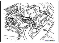
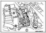
3. Disconnect harness connectors (1) from battery terminal with fusible link.
4. Remove harness fixing clips (A) from F/L·fuse holder bracket.
5. Remove harness fixing clips (A) from F/L·fuse holder bracket.
6. Disconnect harness connector (1) from ECM.
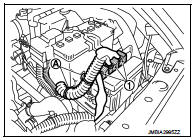
7. Disengage pawl using a flat-bladed screwdriver (A). Remove F/ L·fuse holder.
 : Vehicle front
8. Move F/L·fuse holder and harness to a location where they do not inhibit work.
9. Remove harness fixing clips (A) from F/L·fuse holder bracket.
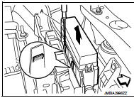
10. Remove mounting bolt (A) and nut (B) of F/L·fuse holder bracket (1), and then remove F/L·fuse holder bracket.
 : Vehicle front
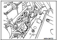
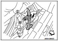
11. Remove mounting bolt (A), and then move water hose (1) and heater thermostat (2) to a location where they do not inhibit work (CVT models).
 : Vehicle front
12. Remove “B” terminal nut and “B” terminal harness.
13. Remove “S” terminal nut and “S” terminal harness.
14. Remove starter motor mounting bolts.
15. Remove starter motor towards vehicle upper.
INSTALLATION
Note the following item, and then install in the reverse order of removal.
CAUTION:
Be careful to tighten “B” terminal nut to the specified torque.
 HR16DE : Exploded View
REMOVAL
1. Cylinder block
2. “B” terminal harness
3. “S” terminal harness
4. Starter motor
: Vehicle front
: N·m (kg-m, in-lb)
: N·m (kg-m, ft-lb)
DISASSEMBLY
Type: M000T32172ZE
1. “M” ...
 HR16DE : Inspection and Adjust
INSPECTION
Magnetic Switch Check
• Before starting to check, disconnect the battery cable from the negative
terminal.
• Disconnect “M” terminal of starter motor.
1. Continuity test [between “S ...
Other materials:
Headlight switch
Lighting
1 Turn the switch to the position:
The front parking, side marker, tail, license plate, instrument lights and daytime
running lights (for NISMO models) will come on.
2 Turn the switch to the position:
Headlights will come on and all the other lights remain on. However, the daytime ...
Combination switch input circuit
Diagnosis Procedure
1.CHECK INPUT 1 - 5 CIRCUIT FOR OPEN
1. Turn ignition switch OFF.
2. Disconnect BCM and combination switch connectors.
3. Check continuity between BCM harness connector and combination switch harness
connector.
Does continuity exist?
YES >> GO TO 2.
NO >> ...
Thermostat
Exploded View
1. Radiator hose (upper)
2. Water inlet
3. Rubber ring
4. Thermostat
A. To radiator
: Always replace after every
disassembly.
: N·m (kg-m, ft-lb)
Removal and Installation
REMOVAL
1. Drain engine coolant from radiator. Refer to CO-37, "Draining".
CAUTION:
P ...
