Nissan Juke Service and Repair Manual : How to select piston and bearing
Description
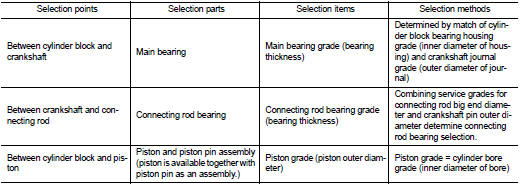
• The identification grade stamped on each part is the grade for the dimension measured in new condition. This grade cannot apply to reused parts.
• For reused or repaired parts, measure the dimension accurately. Determine the grade by comparing the measurement with the values of each selection table.
• For details of the measurement method of each part, the reuse standards and the selection method of the selective fitting parts, refer to the text.
Piston
WHEN NEW CYLINDER BLOCK IS USED
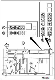
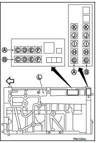
• Check the cylinder bore grade on rear left side of cylinder block (L), and select piston of the same grade.
A : Correction stamp
B : Standard stamp
C : Cylinder No. 1 bore grade
D : Cylinder No. 2 bore grade
E : Cylinder No. 3 bore grade
F : Cylinder No. 4 bore grade
G : No. 1 main bearing housing grade
H : No. 2 main bearing housing grade
I : No. 3 main bearing housing grade
J : No. 4 main bearing housing grade
K : No. 5 main bearing housing grade
 : Engine front
• If there is a correction stamp mark on the cylinder block, use it as a correct reference.
WHEN CYLINDER BLOCK IS REUSED
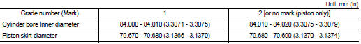
1. Measure the cylinder bore inner diameter. Refer to EM-134, "Cylinder Block".
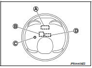
2. Determine the bore grade by comparing the measurement with the values under the cylinder bore inner diameter of the “Piston Selection Table 3. Select piston of the same grade.
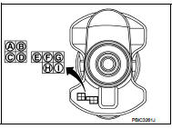
A : Piston grade number
B : Front mark
C : Identification code
D : Sub grade number
PISTON SELECTION TABLE
NOTE
:
Piston is available together with piston pin as an assembly.
Connecting Rod Bearing
WHEN NEW CONNECTING ROD AND CRANKSHAFT ARE USED
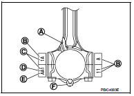
1. Apply connecting rod big end diameter grade stamped on connecting rod side face to the row in the “Connecting Rod Bearing Selection Table”.
A : Oil hole
B : Management code
C : Cylinder number
D : Big end diameter grade
E : Small end diameter grade
F : Front mark
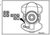
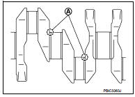
2. Apply crankshaft pin journal diameter grade stamped on crankshaft front side to the column in the “Connecting Rod Bearing Selection Table”.
A : No. 1 pin journal diameter grade B : No. 2 pin journal diameter grade C : No. 3 pin journal diameter grade D : No. 4 pin journal diameter grade E : No. 1 main journal diameter grade F : No. 2 main journal diameter grade G : No. 3 main journal diameter grade H : No. 4 main journal diameter grade I : No. 5 main journal diameter grade
3. Read the symbol at the cross point of selected row and column in the “Connecting Rod Bearing Selection Table”.
4. Apply the symbol obtained to the “Connecting Rod Bearing Grade Table” to select connecting rod bearing.
WHEN CONNECTING ROD AND CRANKSHAFT ARE REUSED
1. Measure the dimensions of the connecting rod big end diameter and crankshaft pin journal diameter individually.
Refer to EM-112, "Inspection".
2. Apply the measured dimension to the “Connecting Rod Bearing Selection Table”.
3. Read the symbol at the cross point of selected row and column in the “Connecting Rod Bearing Selection Table”.
4. Apply the symbol obtained to the “Connecting Rod Bearing Grade Table” to select connecting rod bearing.
CONNECTING ROD BEARING SELECTION TABLE
CONNECTING ROD BEARING GRADE TABLE
Connecting rod bearing grade table : Refer to EM-138, "Connecting Rod Bearing".
UNDERSIZE BEARINGS USAGE GUIDE
• When the specified connecting rod bearing oil clearance is not obtained with standard size connecting rod bearings, use undersize (US) bearings.
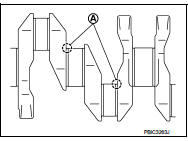
• When using undersize (US) bearing, measure the connecting rod bearing inner diameter with bearing installed, and grind the crankshaft pin so that the connecting rod bearing oil clearance satisfies the standard.
CAUTION
:
In grinding crankshaft pin to use undersize bearings, keep the
fillet R [1.5 - 1.7 mm (0.059 - 0.067 in)] (A
).
Bearing undersize table : Refer to EM-138, "Connecting Rod Bearing".
Main Bearing
WHEN NEW CYLINDER BLOCK AND CRANKSHAFT ARE USED
1. “Main Bearing Selection Table” rows correspond to main bearing housing grade on rear left side of cylinder block (L).
A : Correction stamp
B : Standard stamp
C : Cylinder No. 1 bore grade
D : Cylinder No. 2 bore grade
E : Cylinder No. 3 bore grade
F : Cylinder No. 4 bore grade
G : No. 1 main bearing housing grade
H : No. 2 main bearing housing grade
I : No. 3 main bearing housing grade
J : No. 4 main bearing housing grade
K : No. 5 main bearing housing grade
 : Engine front
• If there is a correction stamp mark on cylinder block, use it as a correct reference.
2. Apply main journal diameter grade stamped on crankshaft front side to column in the “Main Bearing Selection Table”.
A : No. 1 pin journal diameter grade B : No. 2 pin journal diameter grade C : No. 3 pin journal diameter grade D : No. 4 pin journal diameter grade E : No. 1 main journal diameter grade F : No. 2 main journal diameter grade G : No. 3 main journal diameter grade H : No. 4 main journal diameter grade I : No. 5 main journal diameter grade
3. Read the symbol at the cross point of selected row and column in the “Main Bearing Selection Table”.
CAUTION:
There are two main bearing selection tables. One is for No. 1, 4, and 5 journals
and the other is for
No. 2 and 3 journals. Make certain to use the appropriate table. This is due to
differences in the
specified clearances.
4. Apply the symbol obtained to the “Main Bearing Grade Table” to select main bearing.
NOTE
:
Service part is available as a set of both upper and lower.
WHEN CYLINDER BLOCK AND CRANKSHAFT ARE REUSED
1. Measure the dimensions of the cylinder block main bearing housing inner diameter and crankshaft main journal diameter individually. Refer to EM-112, "Inspection".
2. Apply the measured dimension to the “Main Bearing Selection Table”.
3. Read the symbol at the cross point of selected row and column in the “Main Bearing Selection Table”.
CAUTION:
There are two main bearing selection tables. One is for No. 1, 4, and 5 journals
and the other is for
No. 2 and 3 journals. Make certain to use the appropriate table. This is due to
differences in the
specified clearances.
4. Apply the symbol obtained to the “Main Bearing Grade Table” to select main bearing.
NOTE
:
Service part is available as a set of both upper and lower.
MAIN BEARING SELECTION TABLE (No. 1, 4, AND 5 JOURNAL)
MAIN BEARING SELECTION TABLE (No. 2 AND 3 JOURNAL)
MAIN BEARING GRADE TABLE (ALL JOURNALS)
Main bearing grade table (All journals) : Refer to EM-138, "Main Bearing".
UNDERSIZE BEARING USAGE GUIDE
• When the specified main bearing oil clearance is not obtained with standard size main bearings, use undersize (US) bearing.
• When using undersize (US) bearing, measure the main bearing inner diameter with bearing installed, and grind main journal so that the main bearing oil clearance satisfies the standard.
CAUTION
:
In grinding crankshaft main journal to use undersize bearings,
keep the fillet R [1.5 - 1.7 mm (0.059 - 0.067 in)] (A).
Bearing undersize table: Refer to EM-138, "Main Bearing".
 Cylinder block
Exploded View
1. Cylinder block
2. Top ring
3. Second ring
4. Oil ring
5. Piston
6. Piston pin
7. Snap ring
8. Connecting rod
9. Connecting rod bearing (upper)
10. Connecting rod be ...

Other materials:
How to use brightness control and display ON/OFF button
To change the display brightness, push the
button. Pushing the button again will
change the display to the day or the night display.
If no operation is performed within 5 seconds, the display will return to the
previous display.
Push and hold the button for more
than two seconds to turn t ...
B1147 curtain air bag module RH
DTC Logic
DTC DETECTION LOGIC
DTC CONFIRMATION PROCEDURE
1.CHECK SELF-DIAG RESULT
With CONSULT-III
1. Turn ignition switch ON.
2. Perform “Self Diagnostic Result” mode of “AIR BAG” using CONSULT-III.
Without CONSULT-III
1. Turn ignition switch ON.
2. Check the air bag warning lamp statu ...
P0500 VSS
Description
ECM receives vehicle speed signals from two different paths via CAN
communication line: One is from the
ABS actuator and electric unit (control unit) via the combination unit and the
other is from TCM.
DTC Logic
DTC DETECTION LOGIC
NOTE:
• If DTC P0500 is displayed with DTC UXX ...
