Nissan Juke Service and Repair Manual : Headlining
Exploded View
LHD models
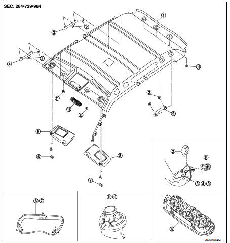
1. Headlining assembly
2. Assist grip clip
3. Rear assist grip RH
4. Front assist grip RH
5. Sun visor assembly RH
6. Sun visor cover RH
7. Sun visor cover LH
8. Sun visor assembly LH
9. Rear assist grip LH
10. Headlining clip
11. Sun visor holder RH
12. Map lamp
13. Sun visor holder LH
14. Metal clip
 : Clip
 : Pawl
Removal and Installation
REMOVAL
CAUTION
:
• When removing, always use a remover tool that is made of plastic.
• Never damage the body.
1. Remove front pillar garnish (LH and RH). Refer to INT-18, "FRONT PILLAR GARNISH : Removal and Installation".
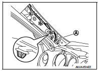
2. Disconnect harness connector (A) from headlining and harness clips.
 : Clip
3. Remove center pillar upper garnish (LH and RH). Refer to INT-21, "CENTER PILLAR UPPER GARNISH : Removal and Installation".
4. Remove back door weather-strip.
• TYPE1: Refer to DLK-170, "BACK DOOR WEATHER-STRIP : Removal and Installation".
• TYPE2: Refer to DLK-333, "BACK DOOR WEATHER-STRIP : Removal and Installation".
• TYPE3: Refer to DLK-468, "BACK DOOR WEATHER-STRIP : Removal and Installation".
• TYPE4: Refer to DLK-584, "BACK DOOR WEATHER-STRIP : Removal and Installation".
5. Remove luggage side upper finisher (LH and RH).INT-32, "LUGGAGE SIDE UPPER FINISHER : Removal and Installation".
6. Remove all assist grips.
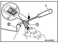
1. Disengage pawl of assist grip clip (1) using a remover tool (A). Slide assist grip clip forward and remove it.
 : Pawl
2. Slide assist grip (2) forward and remove it.
3. Remove metal clips.
7. Remove sun visor assembly (LH and RH).
1. Disengage sun visor cover fixing pawls with a remover tool (A), and then remove sun visor cove
 : Pawl
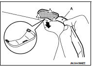
2. Remove sun visor assembly fixing screw, and then remove sun visor assembly.
8. Remove inside mirror and inside mirror cover. Refer to MIR-41, "Removal and Installation".
9. Remove map lamp assembly. Refer to INL-37, "Removal and Installation".
10. Remove front seat assembly (passenger).
• 2WD models: Refer to SE-19, "Removal and Installation".
• 4WD models: Refer to SE-27, "Removal and Installation".
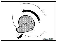
11. Remove sun visor holder (LH and RH).
Rotate 90°. Remove toward vehicle lower.
12. Remove headlining clips.
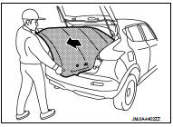
13. Remove headlining assembly through the back door.
CAUTION:
• Two workers are required for removal in order to prevent
damage.
• Apply protective tape to the portion where contact may occur during work.
• Never bend headlining when removing.
INSTALLATION
Note the following items, and install in the reverse order of removal.
CAUTION:
• When installing headlining, start by installing both sun visor holders and
headlining clips in order to
keep the headlining in position.
• Never bend headlining when installing.
• Be careful that the surface is not wrinkled when installing.
 Floor trim
Exploded View
LHD models
1. Floor carpet
2. Carpet hook
3. Trim clip
4. Column hole cover
5. Harness clip
6. Front floor spacer RH
7. Front floor spacer LH
8. Rear floor spacer LH
9. ...
 Luggage floor trim
Exploded View
2WD models
1. Rear pillar cap RH
2. Luggage side upper finisher RH
3. Luggage side lower finisher RH
4. Luggage floor board
5. Luggage side upper finisher LH
6. Rear pillar c ...
Other materials:
Cylinder block
Exploded View
1. Cylinder block
2. Top ring
3. Second ring
4. Oil ring
5. Piston
6. Piston pin
7. Snap ring
8. Connecting rod
9. Connecting rod bearing (upper)
10. Connecting rod bearing (lower)
11. Crankshaft key
12. Connecting rod cap
13. Connecting rod cap bolt
14. Main ...
Removal and installation
POWER WINDOW MAIN SWITCH
Removal and Installation
REMOVAL
1. Remove power window main switch finisher. Refer to INT-13, "Removal and
Installation".
2. Remove power window main switch (1) from power window
main switch finisher (2) using flat-head screw driver (A).
: Pawl
CAUTION:
...
P0089 fuel pump
DTC Logic
DTC DETECTION LOGIC
NOTE:
• Conditions for applying the diagnostic procedure to the stored DTCs:
The DTC becomes present during the first 30 seconds after the engine starts.
• In low ambient temperature conditions, diagnostic cannot make difference
between a normal long engine
st ...
