Nissan Juke Service and Repair Manual : Hazard switch
Component Function Check
1.CHECK HAZARD SWITCH SIGNAL BY CONSULT-III
 CONSULT-III DATA MONITOR
1. Turn the ignition switch ON.
2. Select “HAZARD SW” of BCM (FLASHER) data monitor item.
3. With operating the hazard switch, check the monitor status.
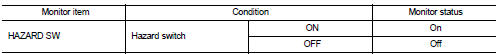
Is the inspection result normal? YES >> Hazard switch circuit is normal.
NO >> Refer to EXL-72, "Diagnosis Procedure".
Diagnosis Procedure
1.CHECK HAZARD SWITCH SIGNAL INPUT
1. Turn ignition switch OFF.
2. Disconnect hazard switch connector.
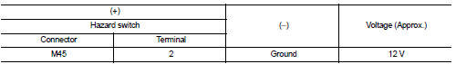
3. Check voltage between hazard switch connector and ground.
Is the inspection result normal? YES >> GO TO 4.
NO >> GO TO 2.
2.CHECK HAZARD SWITCH SIGNAL OPEN CIRCUIT
1. Disconnect BCM connector.
2. Check continuity between hazard switch harness connector and BCM harness connector.
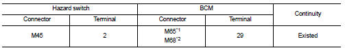
*1: Without Intelligent Key *2: With Intelligent Key
Is the inspection result normal? YES >> GO TO 3.
NO >> Repair or replace harness.
3.CHECK HAZARD SWITCH SIGNAL SHORT CIRCUIT
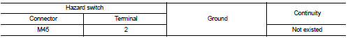
Check continuity between hazard switch harness connector and ground.
Is the inspection result normal?
YES >> Replace BCM. Refer to BCS-93, "Removal and Installation" (with Intelligent Key) or BCS-161, "Removal and Installation" (without Intelligent Key).
NO >> Repair or replace harness.
4.CHECK HAZARD SWITCH GROUND OPEN CIRCUIT
Check continuity between hazard switch harness connector and ground.
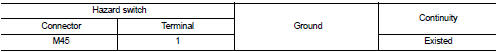
Is the inspection result normal? YES >> Replace hazard switch.
NO >> Repair or replace harness.
 Turn signal lamp circuit
Component Function Check
1.CHECK TURN SIGNAL LAMP
CONSULT-III ACTIVE TEST
1. Select “FLASHER” of BCM (FLASHER) active test item.
2. With operating the test items, check that the turn signal lamps ...

Other materials:
Precaution
Precaution for Supplemental Restraint System (SRS) "AIR BAG" and "SEAT
BELT
PRE-TENSIONER"
The Supplemental Restraint System such as “AIR BAG” and “SEAT BELT PRE-TENSIONER”,
used along
with a front seat belt, helps to reduce the risk or severity of injury to the
driver a ...
B2205 vehicle speed
Description
Vehicle speed signal is transmitted from ABS actuator and electric unit
(control unit) via CAN communication
to combination meter.
DTC Logic
DTC DETECTION LOGIC
Diagnosis Procedure
1.PERFORM SELF-DIAGNOSIS OF ABS ACTUATOR AND ELECTRIC UNIT (CONTROL UNIT)
Perform “Self Diagnost ...
Symptom diagnosis
COMBINATION SWITCH SYSTEM SYMPTOMS
Symptom Table
1. Perform “Data Monitor” of CONSULT-III to check for any malfunctioning
item.
2. Check the malfunction combinations.
3. Identify the malfunctioning part from the agreed combination and repair or
replace the part.
...
