Nissan Juke Service and Repair Manual : Fuel tank
Exploded View
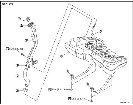
1. Fuel tank cap
2. Grommet
3. Fuel filler tube
4. Clamp
5. Fuel filler hose
6. Clamp
7. Vent hose
8. Fuel tank
9. Mounting band (RH)
10. Mounting band (LH)
 : N·m (kg-m, ft-lb)
Removal and Installation
WARNING:
Be sure to read “General Precautions” when working on the fuel system. Refer to
FL-45, "General Precautions".
REMOVAL
• Drain fuel from fuel tank if necessary. Refer to FL-51, "Removal and Installation".
• Perform work on level place.
1. Remove RH rear wheel.
2. Perform steps 1 to 7 of FL-51, "Exploded View" in “FUEL LEVEL SENSOR UNIT”.
3. Remove center muffler. Refer to EX-17, "Exploded View".
4. Remove insulator on vehicle side located above center muffler.
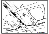
5. Move parking brake cable (1) from the lower face of fuel tank.
Then remove clips for parking brake cable.
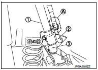
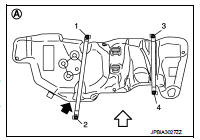
6. Disconnect fuel filler hose at fuel tank sid
1 : Filler tube
2 : Vent hose
3 : Filler hose
A : Quick connector
7. Remove vent hose at RH rear wheelwell side.
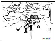
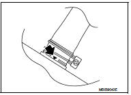
8. Support the center part of fuel tank (1) with transmission jack (A).
CAUTION:
Securely support the fuel tank with a piece of wood (B)
.
9. Remove fuel tank mounting bands (RH/LH).
10. Lower transmission jack carefully to remove fuel tank while holding it by hand.
CAUTION:
Fuel tank may be in an unstable condition because of the shape of fuel tank
bottom. Never rely on
jack too much. Be sure to hold tank securely.
INSTALLATION
Note the following, and install in the reverse order of removal.
Fuel Tank
1. Temporarily tighten bolts [except (2)] in numerical order as
shown in the figure.
A : Under view
 : Vehicle front
2. Tighten bolt (2) to specified torque, pressing fuel tank in the
direction ( ) shown in the
figure.
3. Tighten bolts [except (2)] to specified torque in the reverse order as shown in the figure.
Fuel Filler Hose
• Surely clamp fuel hose insert fuel filler hose to the length below.
Fuel filler hose : 35 mm (1.38 in) The other hose : 25 mm (0.98 in)
• Be sure hose clamp is not placed on swelled area of fuel filler tube.
• Install fuel filler hose to fuel tank, paying attention to install mark.
Marking faces downward.
• Tighten fuel filler hose clamp so that the remaining length of screw thread becomes to the following.
Fuel filler tube side : 8 - 12 mm (0.28 - 0.43 in) Fuel tank side : 5 - 9 mm (0.25 - 0.35 in)
Vent Tube
1. Check connections for damage or foreign material.
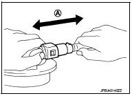
2. Align the matching side connection part with the center of shaft, and insert connector straight until it clicks.
3. After connecting, pull out quick connector and centralized under floor piping by hand. Check connections are secure.
A : Pull
Inspection
INSPECTION AFTER INSTALLATION
Make sure there is no fuel leakage at connections in the following procedure.
• Start engine, rev it up and make sure there is no fuel leakage at connections.
 Fuel level sensor unit
Exploded View
1. Lock ring
2. Fuel level sensor unit
3. Seal packing
A. To fuel tank
: Always replace after every
disassembly
Removal and Installation
WARNING:
Read “General Precautions” ...
 Service data and specifications (SDS)
Fuel tank
...
Other materials:
Key reminder function does not operate
Diagnosis Procedure
1.CHECK DOOR LOCK AND UNLOCK SWITCH
Check door lock and unlock switch.
Refer to DLK-520, "Component Function Check".
Is the inspection result normal?
YES >> GO TO 2.
NO >> Repair or replace the malfunctioning parts.
2.CHECK KEY SWITCH
Check k ...
Vehicle information
BODY EXTERIOR PAINT COLOR
Body Exterior Paint Color
FOR 2WD MODELS
NOTE:
• S: Solid
• 2S: Solid + Clear
• CS: Color clear solid
• M: Metallic
• P: 2-Coat pearl
• 3P: 3-Coat pearl
• FPM: Iron oxide pearl
• RPM: Multi flex color
• TM: Micro titanium metallic
• PM: Pearl metallic
FOR ...
Hazard and buzzer reminder does not operate
Diagnosis Procedure
1.CHECK DTC WITH BCM AND COMBINATION METER
Check that DTC is not detected with BCM and combination meter.
Is the inspection result normal?
YES >> GO TO 2.
NO-1 >> Refer to BCS-67, "DTC Index". (BCM)
NO-2 >> Refer to MWI-36, "DTC Index&qu ...
