Nissan Juke Service and Repair Manual : Fuel tank
Exploded View
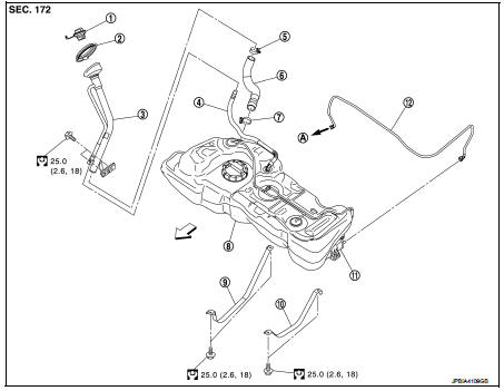
1. Fuel filler cap
2. Grommet
3. Fuel filler tube
4. Vent hose
5. Clamp
6. Fuel filler hose
7. Clamp
8. Fuel tank
9. Fuel tank mounting band (RH)
10. Fuel tank mounting band (LH)
11. EVAP canister
12. EVAP canister hose
A. To fuel tube
 : Vehicle front
 : N·m (kg-m, ft-lb)
Removal and Installation
WARNING:
Be sure to read “General Precautions” when working on the fuel system. Refer to
FL-30, "General Precautions".
REMOVAL
• Drain fuel from fuel tank if necessary. Refer to FL-33, "Removal and Installation".
• Perform work on level place.
1. Remove RH rear wheel.
2. Perform steps 2 to 7 of “REMOVAL” in “FUEL LEVEL SENSOR UNIT, FUEL FILTER AND FUEL PUMP
ASSEMBLY” on fuel level sensor unit, fuel filter and fuel pump assembly. Refer to FL-33, "Removal and Installation".
3. Remove sub muffler. Refer to EM-166, "Removal and Installation".
4. Remove insulator on vehicle side located above center and sub muffler.
5. Remove floor under covers (RH, LH) Refer to EXT-25, "Exploded View".
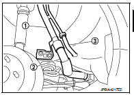
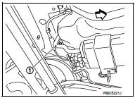
6. Move parking brake cable (1) from the lower face of fuel tank. Then remove clips for parking brake cable.
7. Disconnect fuel filler hose at fuel tank side.
1 : Filler tube
2 : Filler hose
8. Remove vent hose at RH rear wheel well side
9. Remove EVAP canister hose (1) at front side of fuel tank (2).
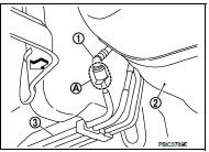
3. : Centralized under-floor piping
A. : quick connector
 : Vehicle front
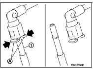
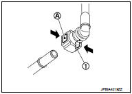
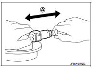
• Remove quick connector in the following procedures.
- Pinch quick connector square-part (A) with your fingers, and pull out the quick connector (1) by hand.
- If quick connector and tube on vehicle are stuck, push and pull several times until they move, and pull out.
CAUTION:
• The tube can be removed when the tabs are completely
depressed. Never twist it more than necessary.
• Never use any tools to disconnect quick connector.
• Keep the resin tube away from heat. Be especially careful when welding near the tube.
• Prevent acid liquid such as battery electrolyte, etc. from getting on the resin tube.
• Never bend or twist resin tube during installation and disconnection.
• To keep the connecting portion clean and to avoid damage and foreign materials, cover them completely with plastic bags or something similar.
• Never insert plug, preventing damage on O-ring in quick connector.
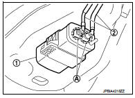
10. Remove EVAP hose (1) in the back for fuel tank side.
 : Vehicle front
11. Remove quick connectors (A) from the EVAP canister (1).
2. : EVAP canister hose
12. Disconnect EVAP hose and vent tube at the position shown in the figure.
• Instruction for quick connector of EVAP hose and vent tube, refer to the following:
Vent hose
• Remove quick connector in the following procedures.
- Pinch quick connector square-part (A) with your fingers, and pull out the quick connector (1) by hand.
- If quick connector and tube on vehicle are stuck, push and pull several times until they move, and pull out.
CAUTION:
• The tube can be removed when the tabs are completely
depressed. Never twist it more than necessary.
• Never use any tools to disconnect quick connector.
• Keep the resin tube away from heat. Be especially careful when welding near the tube.
• Prevent acid liquid such as battery electrolyte, etc. from getting on the resin tube.
• Never bend or twist resin tube during installation and disconnection.
• To keep the connecting portion clean and to avoid damage and foreign materials, cover them completely with plastic bags or something similar.
• Never insert plug, preventing damage on O-ring in quick connector.
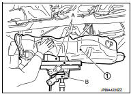
13. Support the center part of fuel tank (1) with transmission jack (B).
CAUTION:
Securely support the fuel tank with a piece of wood (A).
14. Remove fuel tank mounting bands (RH and LH).
15. Lower transmission jack carefully to remove fuel tank while holding it by hand.
CAUTION:
Fuel tank may be in an unstable condition because of the shape of fuel tank
bottom. Never rely on
jack too much. Be sure to hold tank securely.
INSTALLATION
Note the following, and install in the reverse order of removal.
Fuel Tank
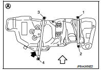
1. Temporarily tighten bolts [except (4)] in numerical order as shown in the figure.
A : Under view
 : Vehicle front
2. Tighten bolt (4) to specified torque, pressing fuel tank in the
direction (  ) shown in the
figure.
3. Tighten bolts [except (4)] to specified torque in the reverse order as shown in the figure.
Fuel Filler Hose
• Surely clamp fuel hose insert fuel filler hose to the length below.
Fuel filler hose : 35 mm (1.38 in) The other hose : 25 mm (0.98 in)
• Be sure hose clamp is not placed on swelled area of fuel filler tube.
• Install fuel filler hose to fuel tank, paying attention to install mark. Marking faces downward.
• Tighten fuel filler hose clamp so that the remaining length of screw thread becomes to the following.
Fuel filler tube side : 8 - 12 mm (0.28 - 0.43 in) Fuel tank side : 5 - 9 mm (0.25 - 0.35 in)
EVAP canister hose
1. Check connections for damage or foreign material.
2. Align the matching side connection part with the center of shaft, and insert connector straight until it clicks.
3. After connecting, pull out quick connector and centralized under floor piping by hand. Check connections are secure.
A : Pull
Inspection
INSPECTION AFTER INSTALLATION
Use the following procedure to check for fuel leakage.
1. Turn ignition switch “ON” (with engine stopped), and check connections for leakage by applying fuel pressure to fuel piping.
2. Start engine and rev it up and check there are no fuel leakage at the fuel system tube and hose connections.
 Fuel level sensor unit, fuel filter and fuel pump assembly
Exploded View
1. Fuel tank
2. Rock ring
3.
Fuel level sensor unit, fuel filter and
fuel pump assembly
4. O-ring
: Vehicle front
: Always replace after every
disassembly.
: N·m (kg-m, ...
 Evap canister
Hydraulic Layout
EVAPORATIVE EMISSION LINE DRAWING
1. EVAP canister purge volume control
solenoid valve
2. Resonator
3. EVAP canister
NOTE:
Do not use soapy water or any type of solvent whil ...
Other materials:
P1632 fuel cut off valve
DTC Logic
DTC DETECTION LOGIC
Diagnosis Procedure
1.CHECK FUEL CUT OFF VALVE POWER SUPPLY CIRCUIT FOR OPEN AND SHORT
1. Turn ignition switch OFF.
2. Disconnect fuel cut off valve harness connector.
3. Turn ignition switch ON.
4. Check the voltage between fuel cut off valve harness connector ...
Sill cover
Exploded View
1. Screw grommet
2. Screw grommet
3. Sill cover
4. Wind defle
Removal and Installation
REMOVAL
1. Remove sill cover front end fixing screw (A).
2. Remove sill cover rear end fixing screw (A).
3. Remove sill cover lower side fixing screws.
4. Fully open front door and ...
Squeak and rattle trouble diagnoses
Work Flow
CUSTOMER INTERVIEW
Interview the customer if possible, to determine the conditions that exist
when the noise occurs. Use the Diagnostic
Worksheet during the interview to document the facts and conditions when the
noise occurs and any of
customer's comments; refer to DLK-302, &quo ...
