Nissan Juke Service and Repair Manual : Fuel pump
Component Function Check
1.CHECK FUEL PUMP FUNCTION
1. Turn ignition switch ON.
2. Pinch fuel feed hose with two fingers.
Fuel pressure pulsation should be felt on the fuel feed hose for 1 second after ignition switch is turned ON.
Is the inspection result normal? YES >> INSPECTION END
NO >> EC-780, "Diagnosis Procedure".
Diagnosis Procedure
1.CHECK FUEL PUMP POWER SUPPLY CIRCUIT-I
1. Turn ignition switch OFF.
2. Disconnect ECM harness connector.
3. Turn ignition switch ON.
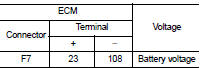
4. Check the voltage between ECM harness connector and ground.
Is the inspection result normal? YES >> GO TO 4.
NO >> GO TO 2.
2.CHECK FUEL PUMP POWER SUPPLY CIRCUIT-II
1. Turn ignition switch OFF.
2. Disconnect IPDM E/R harness connector.
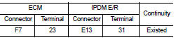
3. Check the continuity between IPDM E/R harness connector and ECM harness connector.
4. Also check harness for short to ground and short to power.
Is the inspection result normal? YES >> GO TO 10.
NO >> GO TO 3.
3.DETECT MALFUNCTIONING PART
Check the following.
• Harness or connectors E8, F1 • IPDM E/R connector E13 • Harness for open or short to ground and short power
>> Repair open circuit or short to ground or short to power in harness or connectors.
4.CHECK FUEL PUMP POWER SUPPLY CIRCUIT-III
1. Turn ignition switch OFF.
2. Reconnect all harness connectors disconnected.
3. Disconnect “fuel level sensor unit and fuel pump” harness connector.
4. Turn ignition switch ON.
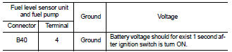
5. Check voltage between “fuel level sensor unit and fuel pump” harness connector and ground.
Is the inspection result normal? YES >> GO TO 8.
NO >> GO TO 5.
5.CHECK 15 A FUSE
1. Turn ignition switch OFF.
2. Disconnect 15 A fuse (No. 60) from IPDM E/R.
3. Check 15 A fuse.
Is the inspection result normal? YES >> GO TO 6.
NO >> Replace fuse.
6.CHECK FUEL PUMP POWER SUPPLY CIRCUIT-IV
1. Disconnect IPDM E/R harness connector.
2. Check the continuity between IPDM E/R harness connector and “fuel level sensor unit and fuel pump” harness connector.
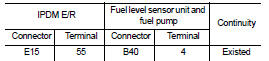
3. Also check harness for short to ground and short to power.
Is the inspection result normal? YES >> GO TO 10.
NO >> GO TO 7.
7.DETECT MALFUNCTIONING PART
Check the following.
• Harness connectors E105, M77 • Harness connectors B1, M18 • Harness for open or short between IPDM E/R and “fuel level sensor unit and fuel pump”
>> Repair open circuit or short to ground or short to power in harness or connectors.
8.CHECK FUEL PUMP GROUND CIRCUIT
1. Check the continuity between “fuel level sensor unit and fuel pump” and ground.
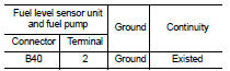
2. Also check harness for short to power.
Is the inspection result normal? YES >> GO TO 9.
NO >> Repair open circuit or short to power in harness or connectors.
9.CHECK FUEL PUMP
Refer to EC-782, "Component Inspection".
Is the inspection result normal? YES >> GO TO 10.
NO >> Replace “fuel level sensor unit and fuel pump”.
10.CHECK INTERMITTENT INCIDENT
Refer to GI-42, "Intermittent Incident".
Is the inspection result normal? YES >> Replace IPDM E/R.
NO >> Repair or replace harness or connectors.
Component Inspection
1.CHECK FUEL PUMP
1. Turn ignition switch OFF.
2. Disconnect “fuel level sensor unit and fuel pump” harness connector.
3. Check resistance between “fuel level sensor unit and fuel pump” terminals as follows.
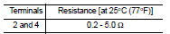
Is the inspection result normal? YES >> INSPECTION END
NO >> Replace “fuel level sensor unit and fuel pump”.
 Fuel injector
Component Function Check
1.INSPECTION START
Turn ignition switch to START.
Is any cylinder ignited?
YES >> GO TO 2.
NO >> Go to EC-778, "Diagnosis Procedure".
2.CHECK ...
 Ignition signal
Component Function Check
1.INSPECTION START
Turn ignition switch OFF, and restart engine.
Does the engine start?
YES-1 >> With CONSULT-III: GO TO 2.
YES-2 >> Without CONSULT-III: ...
Other materials:
Power supply and ground circuit
Diagnosis Procedure
1.CHECK ABS ACTUATOR AND ELECTRIC UNIT (CONTROL UNIT) IGNITION POWER
SUPPLY
1. Turn the ignition switch OFF.
2. Disconnect ABS actuator and electric unit (control unit) harness connector.
3. Check voltage between ABS actuator and electric unit (control unit) harness
conne ...
Periodic maintenance
REAR WHEEL HUB
Inspection
COMPONENT PART
Check the mounting conditions (looseness, back lash) of each component and
component conditions (wear,
damage) are normal.
WHEEL HUB ASSEMBLY (BEARING-INTEGRATED TYPE)
Check the following items, and replace the part it necessary.
• Move wheel hub ...
Inspection
OIL LEAKAGE
Check transfer surrounding area (oil seal, drain plug, filler plug, and
transfer case etc.) for oil leakage.
OIL LEVEL
1. Remove filler plug (1) and gasket. Then check that oil is filled up
from mounting hole for the filler plug.
Vehicle front
CAUTION:
Never start engine while ...
