Nissan Juke Service and Repair Manual : Fuel pressure control
Fuel pressure control : System Diagram
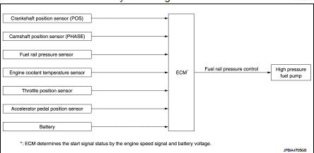
Fuel pressure controlL : System Description
INPUT/OUTPUT SIGNAL CHART
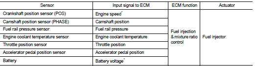
*: ECM determines the start signal status by the engine speed signal and battery voltage.
CVT models
System Description
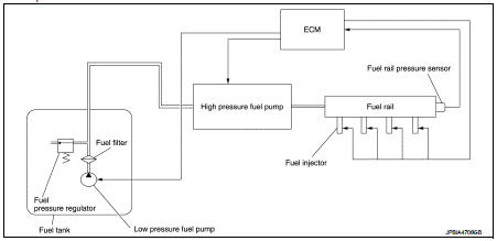
Low fuel pressure control • The low fuel pressure pump is controlled by ECM. The pumped fuel passes through the fuel filter and is sent to the high pressure fuel pump.
• Low fuel pressure is adjusted by the fuel pressure regulator.
High fuel pressure control The high pressure fuel pump raises the pressure of the fuel sent from the low pressure fuel pump. Actuated by the camshaft, the high pressure fuel pump activates the high pressure fuel pump solenoid based on a signal received from ECM, and adjusts the amount of discharge by changing the timing of closing the inlet check valve to control fuel rail pressure.
M/T models
System Description
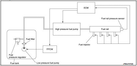
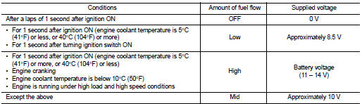
Low fuel pressure control • The low fuel pressure pump is controlled by the fuel pump control module (FPCM) and pumps fuel according to a driving condition. The pumped fuel passes through the fuel filter and is sent to the high pressure fuel pump. FPCM controls the low pressure fuel pump, according to a signal from ECM as shown in the table below.
• Low fuel pressure is adjusted by the fuel pressure regulator.
High fuel pressure control The high pressure fuel pump raises the pressure of the fuel sent from the low pressure fuel pump. Actuated by the camshaft, the high pressure fuel pump activates the high pressure fuel pump solenoid based on a signal received from ECM, and adjusts the amount of discharge by changing the timing of closing the inlet check valve to control fuel rail pressure
 Direct injection gasoline system
Direct injection gasoline system : System Diagram
Direct injection gasoline system : System Description
INPUT/OUTPUT SIGNAL CHART
*1: This sensor is not used to control the engine system under ...
 Electric ignition system
Electric ignition system : System Diagram
Electric ignition system : System Description
INPUT/OUTPUT SIGNAL CHART
*1: CVT models
*2: M/T models
*3: ECM determines the start signa ...
Other materials:
P2263 TC system
DTC Logic
DTC DETECTION LOGIC
Diagnosis Procedure
1.CHECK VACUUM HOSES AND VACUUM GALLERY
1. Turn ignition switch OFF.
2. Check vacuum hoses and vacuum gallery for clogging, cracks
or improper connection. Refer to EC-825, "TURBOCHARGER
BOOST CONTROL : Vacuum Hose Drawing".
Is t ...
P0138 HO2S2
DTC Logic
DTC DETECTION LOGIC
The heated oxygen sensor 2 has a much longer switching time between rich and
lean than the air fuel ratio (A/
F) sensor 1. The oxygen storage capacity of the three way catalyst 1 causes the
longer switching time.
MALFUNCTION A
To judge the malfunctions of hea ...
Hood
Exploded View
1. Hood assembly
2. Hood bumper rubber
3. Radiator core seal
4. Hood bumper rubber
5. Clamp
6. Hood hinge
7. Grommet
8. Hood support rod
: Clip
: Pawl
: Body grease
Hood assembly
HOOD ASSEMBLY : Removal and Installation
CAUTION:
• Operate with two workers, because ...
