Nissan Juke Service and Repair Manual : Fuel level sensor unit
Exploded View
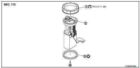
1. Lock ring
2. Fuel level sensor unit
3. Seal packing
A. To fuel tank
 : Always replace after every
disassembly
Removal and Installation
WARNING:
Read “General Precautions” when working on the fuel system. Refer to FL-45,
"General Precautions".
REMOVAL
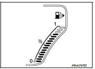
1. Check fuel level on fuel gauge. If fuel gauge indicates more than the level as shown in the figure (full or almost full), drain fuel from fuel tank until fuel gauge indicates level as shown in the figure or below.
NOTE
:
Because fuel will be spilled when removing fuel level sensor
units for the top of the fuel is above the fuel level sensor units
installation surface.
• As a guide, fuel level becomes the position as shown in the figure or below when approximately 10 (2-5/8 US gal, 2-1/4 Imp gal) of fuel are drained from fuel tank.
• In a case that fuel pump does not operate, perform the following procedure
a. Insert hose of less than 25 mm (0.98 in) in diameter into fuel filler tube through fuel filler opening to draw fuel from fuel filler tube.
b. Disconnect fuel filler hose from fuel filler tube. Refer to FL-55, "Exploded View".
c. Insert hose into fuel tank through fuel filler hose to draw fuel from fuel tank.
2. Open fuel filler lid.
3. Open filler cap and release the pressure inside fuel tank.
4. Remove rear seat. Refer to SE-32, "Exploded View".
5. Remove inspection hole cover.
• Using a screwdriver, remove it by turning clips clockwise by 90 degrees.
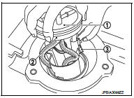
6. Disconnect harness connector (1), fuel feed tube (4) and quick connector (3).
2 : Fuel level sensor unit
 : Vehicle front
• Hold the connector while pushing in tabs, and pull out the tube.
CAUTION:
• Quick connector can be removed when the tabs are completely depressed. Never
twist it more
than necessary.
• Never use any tools to disconnected quick connector.
• Keep resin tube away from heat. Be especially careful when welding near the resin tube.
• Prevent acid liquid such as battery electrolyte, etc. from getting on resin tube.
• Never bend or twist resin tube during installation and disconnection.
• To keep the connecting portion clean and to avoid damage and foreign materials, cover them completely with plastic bags (A) or something similar.
• Never insert plug, preventing damage on O-ring in quick connector.
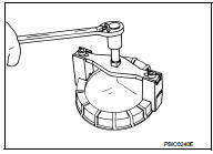
![7. Using lock ring wrench [SST: KV99104700 (Mot.1397)], remove lock ring.](images/books/335/21/index268.jpg)
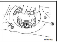
7. Using lock ring wrench [SST: KV99104700 (Mot.1397)], remove lock ring.
CAUTION:
Rotate SST while pressing fuel level sensor unit as spring reaction force is
applied from fuel tank
inside to up ward.
8. Remove fuel level sensor unit.
2 : O-ring
CAUTION:
• Be careful not to bend the float arm (3) when removing.
• Handle them carefully without subjecting them to impacts such as dropping.
INSTALLATION
Note to the following, and install in the reverse order of removal.
Fuel Level Sensor Unit
1. Temporarily install the O-ring to the fuel level sensor unit.
2. Insert the fuel level sensor unit to the fuel tank, and then install the temporarily installed O-ring (Step 1) to the opening of the fuel tank.
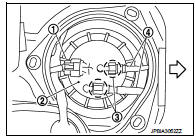
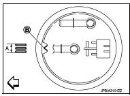
3. Install fuel level sensor unit to fuel tank with alignment mark (B) on the upper surface facing the tree inscribed lines (A) on the tank side.
 : Vehicle front
CAUTION:
• Never allow O-ring to drop.
• Never bend float arm during installing.
4. Install lock ring for fuel level sensor unit, fuel filter and fuel pump assembly with lock ring wrench [SST: KV993G0010 (Mot. 1397)] by turning clockwise.
CAUTION:
Install lock ring horizontally.
Quick Connector
Connect quick connector as follows:
1. Check the connection for damage or any foreign materials.
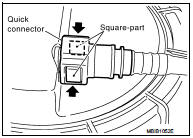
2. Align the connector with the tube, then insert the connector straight into the tube until a click sound is heard.
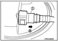
3. After connecting, check that the connection is secure by following method.
• Visually confirm that the two tabs are connected to the connector.
• Pull (A) the tube and the connector to check they are securely connected.
1 : Quick connector

 Fuel tank
Exploded View
1. Fuel tank cap
2. Grommet
3. Fuel filler tube
4. Clamp
5. Fuel filler hose
6. Clamp
7. Vent hose
8. Fuel tank
9. Mounting band (RH)
10. Mounting band (LH)
: N·m (kg- ...
Other materials:
Refrigeration system symptoms
Trouble Diagnosis For Unusual Pressure
Diagnose using a manifold gauge whenever system’s high and/or low side
pressure(s) is/are unusual. The
marker above the gauge scale in the following tables indicates the standard
(usual) pressure range. Refer to
above table (Ambient air temperature-to-op ...
Side oil seal
Removal and Installation
REMOVAL
1. Remove front drive shafts. Refer to FAX-53, "Removal and Installation".
2. Remove differential side oil seals (1) from clutch housing and
transaxle case, using an oil seal remover.
CAUTION:
Never damage transaxle case and clutch housing.
INSTA ...
Electric power steering system
WARNING
• If the engine is not running or is turned off while driving, the power assist
for the steering will not work.
Steering will be harder to operate.
• When the electric power steering warning light illuminates with the engine
running, the power assist for the steering will cease ...
