Nissan Juke Service and Repair Manual : Fuel level sensor signal circuit
Component Function Check
2WD MODELS
1.CHECK COMBINATION METER OUTPUT SIGNAL
Select the “Data Monitor” for the “METER/M&A” and compare the “FUEL METER” monitor value with the fuel gauge reading on the combination meter.
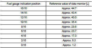
Does monitor value match fuel gauge reading? YES >> INSPECTION END
NO >> Replace combination meter. Refer to MWI-69, "Removal and Installation".
4WD MODELS
1.CHECK COMBINATION METER OUTPUT SIGNAL
Select the “Data Monitor” for the “METER/M&A” and compare the “FUEL METER” monitor value with the fuel gauge reading on the combination meter.
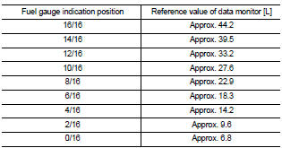
Does monitor value match fuel gauge reading? YES >> INSPECTION END
NO >> Replace combination meter. Refer to MWI-69, "Removal and Installation".
Diagnosis Procedure
1.CHECK COMBINATION METER INPUT SIGNAL
1. Turn ignition switch ON.
2. Check voltage between combination meter harness connector and ground.
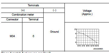
Does it match fuel gauge reading? YES >> GO TO 2.
NO >> Replace the combination meter. Refer to MWI-69, "Removal and Installation".
2.CHECK FUEL LEVEL SENSOR CIRCUIT
1. Turn ignition switch OFF.
2. Disconnect combination meter connector and fuel level sensor unit connector.
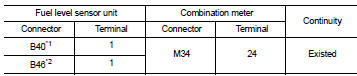
3. Check continuity between combination meter harness connector terminal and fuel level sensor unit harness connector terminal.
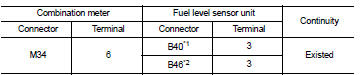
*1: 2WD models
*2: 4WD models
4. Check continuity between combination meter harness connector terminal and ground.
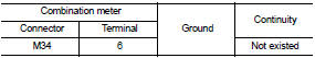
Is the inspection result normal? YES >> GO TO 3.
NO >> Repair harness or connector.
3.CHECK FUEL LEVEL SENSOR GROUND CIRCUIT
Check continuity between fuel level sensor unit harness connector terminal and combination meter harness connector terminal.
*1: 2WD models
*2: 4WD models
Is the inspection result normal? YES >> INSPECTION END
NO >> Repair harness or connector.
Component Inspection
2WD MODELS
1.REMOVE FUEL LEVEL SENSOR UNIT (MAIN)
Remove the fuel level sensor unit (main). Refer to FL-6, "2WD : Removal and Installation" (MR16DDT), FL-33, "Removal and Installation" (HR16DE), or FL-51, "Removal and Installation" (K9K).
>> GO TO 2.
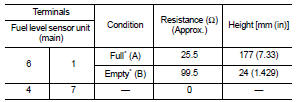
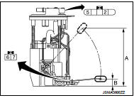
2.CHECK FUEL LEVEL SENSOR UNIT (MAIN)
Check the resistance between fuel level sensor unit and fuel pump.
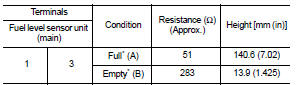
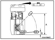
*: When float rod is contact with stopper.
Is inspection result OK? YES >> INSPECTION END
NO >> Replace the fuel level sensor unit (main). Refer to FL-6, "2WD : Removal and Installation" (MR16DDT), FL-33, "Removal and Installation" (HR16DE), or FL-51, "Removal and Installation" (K9K).
4WD MODELS
1.REMOVE FUEL LEVEL SENSOR UNIT (MAIN)
Remove the fuel level sensor unit (main). Refer to FL-11, "4WD : Removal and Installation".
>> GO TO 2.
2.CHECK FUEL LEVEL SENSOR UNIT (MAIN)
Check the resistance between fuel level sensor unit and fuel pump.
*: When float rod is contact with stopper.
Is inspection result OK? YES >> GO TO 3.
NO >> Replace fuel level sensor unit (main). Refer to FL-11, "4WD : Removal and Installation".
3.REMOVE FUEL LEVEL SENSOR UNIT (SUB)
Remove the fuel level sensor unit (sub). Refer to FL-11, "4WD : Removal and Installation".
>> GO TO 4.
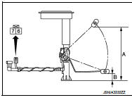
4.CHECK FUEL LEVEL SENSOR UNIT (SUB)
Check the resistance between fuel level sensor unit (sub).
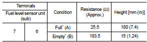
*: When float rod is contact with stopper.
Is inspection result OK? YES >> INSPECTION END
NO >> Replace fuel level sensor unit (sub). Refer to FL-11, "4WD : Removal and Installation".
 Power supply and ground circuit
Combination meter
COMBINATION METER : Diagnosis Procedure
1.CHECK FUSE
Check for blown fuses.
Is the inspection result normal?
YES >> GO TO 2.
NO >> Be sure to eliminate cause of ...
 Oil pressure switch signal circuit
Component Function Check
1.CHECK COMBINATION METER INPUT SIGNAL
Select the “Data Monitor” for the “METER/M&A” and check the “OIL W/L” monitor
value.
“OIL W/L”
Ignition switch ON : On
Engine ...
Other materials:
Inside key antenna
Instrument center
INSTRUMENT CENTER : Removal and Installation
REMOVAL
1. Remove the multi display unit. Refer to AV-125, "Removal and
Installation".
2. Remove the inside key antenna (instrument center) (1) mounting
clip (A), and then remove inside key antenna (instrument
center).
...
Air conditioner filter
Exploded View
LHD models
1. A/C unit assembly
2. Air conditioner filter
3. Filter cover
Removal and Installation (LHD models)
REMOVAL
1. Remove glove box assembly. Refer to IP-13, "Removal and Installation".
2. Remove filter cover (1), and then remove air conditioner filter (2) ...
Normal operating condition
INFORMATION DISPLAY
INFORMATION DISPLAY : Description
AMBIENT TEMPERATURE
The displayed ambient temperature on the information display may differ from
the actual temperature because
it is a corrected value calculated from the ambient sensor signal by the
combination meter. Refer to MWI-16,
...
