Nissan Juke Service and Repair Manual : Fuel injector and fuel tube
Exploded View
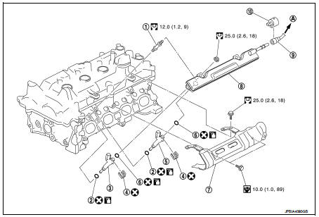
1. Stud bolt
2. O-ring (green)
3. Fuel injector (front)
4. Clip
5. Fuel injector (rear)
6. O-ring (black)
7. Fuel tube protector
8. Fuel tube
9. Fuel feed hose
10. Quick connector cap
A. To centralized under-floor piping
 : Always replace after every
disassembly.
 : N·m (kg-m, in-lb)
 : N·m (kg-m, ft-lb)
 : Should be lubricated with oil.
CAUTION:
Never remove or disassemble parts unless instructed as shown in the figure.
Removal and Installation
WARNING:
• Put a “CAUTION: FLAMMABLE” sign in the workshop.
• Be sure to work in a well ventilated area and furnish workshop with a CO2 fire extinguisher.
• Never smoke while servicing fuel system. Keep open flames and sparks away from the work area.
REMOVAL
1. Release the fuel pressure. Refer to EC-551, "Work Procedure".
2. Remove intake manifold. Refer to EM-163, "Exploded View".
3. Disconnect quick connector with the following procedure. Disconnect fuel feed hose from fuel tube.
1 : Quick connector cap
NOTE
:
There is no fuel return path.
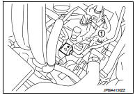
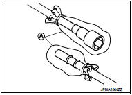
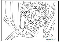
a. Remove quick connector cap (engine side) (1) from quick connector connection.
b. Disconnect fuel feed hose from hose clamp.
c. With the sleeve side of quick connector release facing quick connector, install quick connector release (commercial service tool) onto fuel tube.
d. Insert quick connector release (A) into quick connector (2) until sleeve (B) contacts and goes no further. Hold quick connector release on that position.
D : Insert and retain
CAUTION:
Inserting quick connector release hard will not disconnect
quick connector. Hold quick connector release where it
contacts and goes no further.
e. Draw and pull out quick connector straight from fuel tube (1).
CAUTION:
• Pull quick connector (E) holding position (C) in the figure.
• Never pull with lateral force applied. O-ring inside quick connector may be damaged.
• Prepare container and cloth beforehand as fuel will leakage out.
• Avoid fire and sparks.
• Keep parts away from heat source. Especially, be careful when welding is performed around them.
• Never expose parts to battery electrolyte or other acids.
• Never bend or twist connection between quick connector and fuel feed tube during installation/ removal.
• To keep clean the connecting portion and to avoid damage and foreign materials, cover them completely with plastic bags, etc. (A) or something similar.
4. Disconnect harness connector from fuel injector.
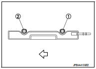
5. Remove fuel tube protector.
• Loosen mounting bolts in reverse order as shown in the figure.
 : Engine front
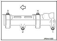
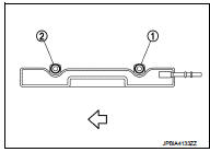
6. Remove fuel tube and fuel injector assembly.
• Loosen mounting bolts in reverse order as shown in the figure.
 : Engine front
CAUTION:
• When removing, be careful to avoid any interference with fuel
injector.
• Use a shop cloth to absorb any fuel leakage from fuel tube.
7. Remove fuel injector from fuel tube with the following procedure: a. Open and remove clip (1).
b. Remove fuel injector (3) and (4) from fuel tube (2) by pulling straight.
CAUTION:
• Be careful with remaining fuel that may go out from fuel
tube.
• Be careful not to damage fuel injector nozzle during removal.
• Never bump or drop fuel injector.
• Never disassemble fuel injector.

INSTALLATION
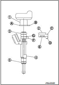
1. Note the following, and install O-rings to fuel injector.
CAUTION:
• Upper and lower O-rings are different. Be careful not to confuse them.
Fuel tube side : Black Nozzle side : Gre
• Handle O-ring with bare hands. Never wear gloves.
• Lubricate O-ring with new engine oil.
• Never clean O-ring with solvent.
• Check that O-ring and its mating part are free of foreign material.
• When installing O-ring, be careful not to scratch it with tool or fingernails. Also be careful not to twist or stretch O-ring. If O-ring is stretched while installing, never insert it quickly into fuel tube.
• Insert O-ring straight into fuel tube. Never decenter or twist it.
2. Install fuel injector to fuel tube with the following procedure:
a. Insert clip (2) into clip mounting groove on fuel injector (4).
3 : O-ring (black)3 : O-ring (black) 5 : O-ring (green) 5 : O-ring (green)
• Insert clip so that protrusion (F) of fuel injector matches cut-out (D) of clip.
CAUTION:
• Never reuse clip. Replace it with a new one.
• Be careful to keep clip from interfering with O-ring. If interference occurs, replace O-ring.
b. Insert fuel injector into fuel tube (1) with clip attached.
• Insert it while matching it to the axial center.
• Insert fuel injector so that protrusion (B) of fuel tube matches cut-out (C) of clip.
• Check that fuel tube flange (A) is securely fixed in flange fixing groove (E) on clip.
c. Check that installation is complete by checking that fuel injector does not rotate or come off.
3. Set fuel tube and fuel injector assembly at its position for installation on cylinder head.
CAUTION:
For installation, be careful not to interfere with fuel injector nozzle.
4. Install fuel tube and injector assembly onto cylinder.
• Tighten mounting bolts in numerical order as shown in the figure.
 : Engine front
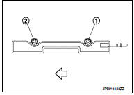
5. Install fuel tube protector.
• Tighten mounting bolts in numerical order as shown in the figure.
 : Engine front
6. Connect harness connector to fuel injector.
7. Connect fuel feed tube with the following procedure.
a. Check for damage or foreign material on the fuel tube and quick connector.
b. Apply new engine oil lightly to area around the top of fuel tube.
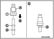
c. Align center to insert quick connector straightly into fuel tube.
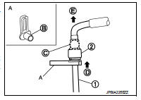
• Insert quick connector (1) to fuel tube until the top spool (C) on fuel tube is inserted completely and the 2nd level spool (D) is positioned slightly below quick connector bottom end.
B : Upright insertion E : Fitted condition
CAUTION:
• Hold (A) position in the figure when inserting fuel tube
into quick connector.
• Carefully align center to avoid inclined insertion to prevent damage to O-ring inside quick connector.
• Insert until you hear a “click” sound and actually feel the engagement.
• To avoid misidentification of engagement with a similar sound, be sure to perform the next step.
d. Pull quick connector hard by hand holding position. Check it is completely engaged (connected) so that it does not come out from fuel tube.
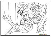
e. Install quick connector cap (engine side) (1) to quick connector connection.
• Install quick connector cap (engine side) with the side arrow facing quick connector side (fuel feed tube side).
CAUTION:
• Check that the quick connector and fuel tube are
securely engaged with the quick connector cap (engine
side) mounting groove.
• Quick connector may not be connected correctly if quick connector cap (engine side) cannot be installed easily. Remove the quick connector cap (engine side), and then check the connection of quick connector again.
f. Install fuel feed hose to hose clamp.
8. Install remaining parts in the reverse order of removal.
Inspection
INSPECTION AFTER INSTALLATION
Check on Fuel Leakage 1. Turn ignition switch “ON” (with the engine stopped). With fuel pressure applied to fuel piping, check there are no fuel leakage at connection points.
NOTE
:
Use mirrors for checking at points out of clear sight.
2. Start the engine. With engine speed increased, check again that there are no fuel leakage at connection points.
CAUTION:
Never touch the engine immediately after stopped, as the engine becomes
extremely hot.
 Oil pan (lower)
Exploded View
With Oil Cooler
1. Rear oil seal
2. O-ring
3. Oil pan (upper)
4. Oil pump chain tensioner (for oil
pump drive chain)
5. Oil pump drive chain
6. Crankshaft sprocket
7. Oil ...
 Ignition coil, spark plug and rocker cover
Exploded View
1. Ignition coil
2. Spark plug
3. Rocker cover
4. Hose cramp
5. PCV hose
6. PCV valve
7. O-ring
8. Gasket
9. Oil filler cap
10. O-ring
11. Camshaft position sensor (I ...
Other materials:
ECM branch line circuit
Diagnosis Procedure
1.CHECK CONNECTOR
1. Turn the ignition switch OFF.
2. Disconnect the battery cable from the negative terminal.
3. Check the terminals and connectors of the ECM for damage, bend and loose
connection (unit side and
connector side).
Is the inspection result normal?
YES &g ...
How to select piston and bearing
Description
• The identification grade stamped on each part is the grade for the
dimension measured in new condition. This grade cannot apply to reused parts.
• For reused or repaired parts, measure the dimension accurately. Determine the
grade by comparing the
measurement with the values o ...
B2110 shift position/clutch interlock switch
DTC Logic
DTC DETECTION LOGIC
NOTE:
If DTC B2110 is displayed with DTC U1000, first perform the trouble diagnosis
for DTC U1000. Refer to PCS-
30, "DTC Logic".
DTC CONFIRMATION PROCEDURE
1.PERFORM DTC CONFIRMATION PROCEDURE
1. Shift selector lever to the P position.
2. Turn ign ...
