Nissan Juke Service and Repair Manual : Fuel filter
Exploded View
Removal and Installation
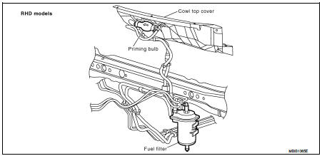
REMOVAL (RHD)
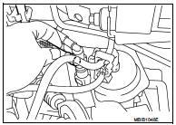
1. Remove quick connectors in the following procedures.
• Pinch quick connector square-parts with your fingers, and pull out the quick connector by hand.
• If quick connector and tube on vehicle are stuck, push and pull several times until they move, and pull out.
2. Remove fuel filter from fuel filter bracket.
CAUTION:
Never spill the fuel during removal. If the fuel is spill, immediately
wipe it off. Be especially careful to prevent the fuel
from adhering to the insulators of the engine mounts.
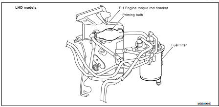
REMOVAL (LHD)
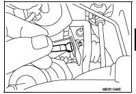
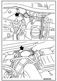
1. Remove priming bulb from priming bulb bracket.
2. Remove fuel filter from fuel filter bracket.
3. Remove quick connectors as above.
CAUTION:
Put a shop cloth under the drain valve, to avoid the water and fuel spill on ABS
actuator. Be especially
careful to prevent any damage.
INSTALLATION
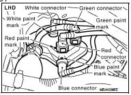
Install in the reverse order of removal, paying attention to the following points: • To install fuel filter connectors, respect paint marks on fuel filter as shown.
• After installation, operate the priming bulb vertically, if it is possible, to perform air bleeding.
Refer to FL-50, "Air Bleeding".
CAUTION:
Never bend or twist the tube during installation and removal.
Water Draining
DRAINING WATER (RHD)
CAUTION:
Before carrying out any work, wait for the fuel temperature is dropped.
Open drain valve at the bottom of fuel filter.
DRAINING WATER (LHD)
1. Remove fender protector RH. Refer to EXT-22, "Exploded View".
2. Remove foam insulator.
3. Open drain valve at the bottom of fuel filter.
CAUTION:
Put a shop cloth under the drain valve, to avoid the water and fuel spill on ABS
actuator
.
FUEL FILTER CHECK
Check fuel filter for fuel leakage, damage and other abnormal signs.
Air Bleeding
1. Prime the circuit using the priming bulb.
2. Perform engine cranking with repeating several times until engine starting.
3. If the engine does not start, perform the following procedure.
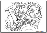
2 : High pressure supply pump
a. Remove high pressure pump protector. Refer to EM-298, "Exploded View".
b. Remove quick connector (black tab).
c. Connect drain hose (suitable hose) (1) to the end of quick connector (supply pipe side) (3).
d. Place a tray (4) at the drain hose open end.
e. Operate the priming bulb to completely bleed air from the circuit.
4. When air bleeding is completed, install quick connector, and check absence of leakage.
 Fuel system
Checking Fuel Line
Inspect fuel lines and tank for improper attachment, leaks, cracks,
damage, chafing and deterioration.If necessary, repair or replace.
...

Other materials:
Service Notice or Precautions for Manual Transaxle
CAUTION:
• Never reuse CSC (Concentric Slave Cylinder). Because CSC slides back to the
original position
every time when removing transaxle assembly. At this timing, dust on the sliding
parts may damage
a seal of CSC and may cause clutch fluid leakage. Refer to CL-27, "Removal and
Inst ...
Parking brake switch signal circuit
Diagnosis Procedure
1.CHECK COMBINATION METER INPUT SIGNAL
1. Turn ignition switch ON.
2. Check the voltage between combination meter harness connector and ground.
Is the inspection result normal?
YES >> INSPECTION END
NO >> GO TO 2.
2.CHECK PARKING BRAKE SWITCH SIGNAL CIRCUIT ...
B1065, B1070 passenger air bag module
DTC Logic
DTC DETECTION LOGIC
DTC CONFIRMATION PROCEDURE
1.CHECK SELF-DIAG RESULT
With CONSULT-III
1. Turn ignition switch ON.
2. Perform “Self Diagnostic Result” mode of “AIR BAG” using CONSULT-III.
Without CONSULT-III
1. Turn ignition switch ON.
2. Check the air bag warning lamp statu ...
