Nissan Juke Service and Repair Manual : Front wiper arm
Exploded View
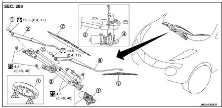
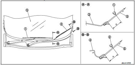
RHD models

1. Front wiper arm cap
2. Front wiper arm RH
3. Front wiper drive assembly
4. Front wiper motor
5. Front wiper blade LH
6. Front wiper arm LH
7. Front wiper blade RH
 : Pawl
 : N·m (kg-m, in-lb)
 : N·m (kg-m, ft-lb)
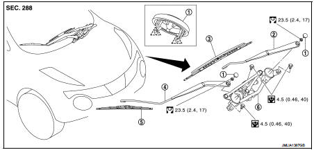
LHD models
1. Front wiper arm cap
2. Front wiper arm LH
3. Front wiper blade LH
4. Front wiper arm RH
5. Front wiper blade RH
6. Front wiper drive assembly
 : Pawl
 : N·m (kg-m, in-lb)
 : N·m (kg-m, ft-lb)
Removal and Installation
REMOVAL
1. Operate front wiper to move it to the auto stop position.
2. Open the hood.
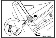
3. Disengage front wiper arm cap (1) fixing pawls with a remover tool (A), and then remove front wiper arm cap from the wiper arm (2).
 : Pawl
 : Vehicle front
4. Remove front wiper arm mounting nuts.
5. Raise front wiper arm, and then remove front wiper arm from the vehicle.
INSTALLATION
1. Clean wiper arm mount as shown in the figure to prevent nuts from being loosened.
2. Operate front wiper motor to move the front wiper to the auto stop position.
3. Adjust front wiper blade position. Refer to WW-76, "Adjustment".
4. Install front wiper arm by tightening the mounting nuts.
5. Inject the washer fluid.
6. Operate front wiper to move it to the auto stop position.
7. Check that the front wiper blades stop at the specified position.
8. Install front wiper arm caps.
Adjustment
WIPER BLADE POSITION ADJUSTMENT
Clearance between the end of cowl top cover/ front fender protector and the top of wiper blade center NOTE
:
This figure is for RHD models and is symmetric with LHD models
1. Front wiper blade RH
2. Front wiper blade LH
3. Cowl top cover
4. Front fender cover
5. Windshield glass assembly
Standard clearance
D : 37.7 ± 7.5 mm (1.484 ± 0.295 in) P : 46.8 ± 7.5 mm (1.843 ± 0.295 in)
 Front washer nozzle and tube
Exploded View
LHD models
1. Front washer nozzle LH
2. Front washer nozzle RH
3. Cowl top cover
4. Front washer tube (tank side)
5. Front washer tube RH
6. Front washer tube LH
: Vehicle ...
 Front wiper blade
Exploded View
1. Wiper blade
2. Wiper arm
Removal and Installation
REMOVAL
Push up the lever (A) of wiper blade (1), while sliding wiper blade
toward the direction of the arrow to remove it f ...
Other materials:
Horn function
Component Function Check
1.CHECK FUNCTION 1
1. Disconnect vehicle security horn relay.
2. Perform “VEHICLE SECURITY HORN” in “ACTIVE TEST” mode of “THEFT ALM” of “BCM”
using CONSULT-
III.
3. Check the horn operation.
Is the operation normal?
YES >> GO TO 2.
NO >> Go to SE ...
Connector Symbols
Most of connector symbols in wiring diagrams are shown from the terminal
side.
• Connector symbols shown from the terminal side are enclosed by
a single line and followed by the direction mark.
• Connector symbols shown from the harness side are enclosed by
a double line and followed by the ...
Rear disc brake
Brake pad : Exploded View
1. Sliding pin bolt
2. Cylinder body
3. Inner shim cover
4. Inner shim
5. Inner pad (with pad wear sensor)
6. Pad retainer
7. Torque member
8. Outer pad
9. Outer shim
10. Outer shim cover
1 Apply rubber grease.
2: Apply MOLYKOTE® AS880N or
silicone-bas ...
