Nissan Juke Service and Repair Manual : Front stabilizer
Exploded View
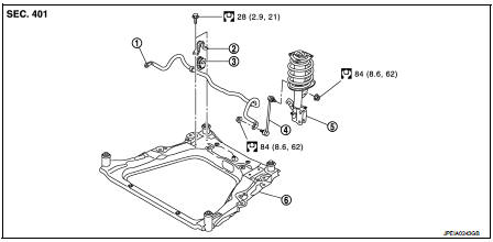
1. Stabilizer bar
2. Stabilizer clamp
3. Stabilizer bushing
4. Stabilizer connecting rod
5. Strut assembly
6. Front suspension member
 : N·m (kg-m, ft-lb)
Removal and Installation
REMOVAL
1. Remove tires. Refer to WT-7, "Removal and Installation".
2. Remove front suspension member. Refer to FSU-18, "Removal and Installation".
3. Remove stabilizer connecting rod.
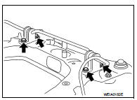
4. Remove mounting bolts ( ) of
) of
stabilizer clamp, and then
remove stabilizer clamp and stabilizer bushing from front suspension
member.
5. Remove stabilizer bar.
6. Perform inspection after removal. Refer to FSU-17, "Inspection".
INSTALLATION
Note the following, and install in the reverse order of removal.
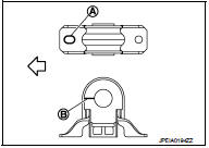
• Install stabilizer clamp and stabilizer bush with notch (A) and slit (B) faced forward of the vehicle ( ).
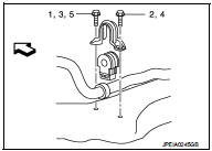
• To install stabilizer clamp mounting bolt, follow the tightening method and the numerical order shown below:
Manual tightening : 1 Temporary tightening : 2 → 3 Final tightening (Specified torque) : 4 → 5
 : Vehicle front
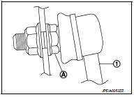
• To install stabilizer connecting rod (1), tighten the mounting nut with the hexagonal part (A) on the stabilizer connecting rod side fixed.
• Perform final tightening of bolts and nuts at the vehicle installation position (rubber bushing), under unladen conditions with tires on level ground.
• Perform inspection after installation. Refer to FSU-14, "Inspection".
Inspection
INSPECTION AFTER REMOVAL
Check stabilizer bar, stabilizer connecting rod, stabilizer bushing and stabilizer clamp for deformation, cracks or damage. Replace it if necessary.
INSPECTION AFTER INSTALLATION
Check wheel alignment. Refer to FSU-7, "Inspection".
 Transverse link
Exploded View
1. Front suspension member
2. Transverse link
: Always replace after every
disassembly.
: N·m (kg-m, ft-lb)
Removal and Installation
REMOVAL
1. Remove tires. Refer to WT-7, & ...
 Front suspension member
Exploded View
2WD
1. Front suspension member
2. Damper assembly*
3. Rebound stopper rubber
4. Washer
5. Member stay
6. Rebound stopper
: N·m (kg-m, ft-lb)
*: For K9K models
4WD
1. F ...
Other materials:
Vehicle information
BODY EXTERIOR PAINT COLOR
Body Exterior Paint Color
FOR 2WD MODELS
NOTE:
• S: Solid
• 2S: Solid + Clear
• CS: Color clear solid
• M: Metallic
• P: 2-Coat pearl
• 3P: 3-Coat pearl
• FPM: Iron oxide pearl
• RPM: Multi flex color
• TM: Micro titanium metallic
• PM: Pearl metallic
FOR ...
P1864 input speed signal
DTC Logic
DTC DETECTION LOGIC
DTC CONFIRMATION PROCEDURE
1.PRECONDITIONING
If “DTC CONFIRMATION PROCEDURE” has been previously conducted, always turn
ignition switch OFF and
wait at least 10 seconds before conducting the next test.
>> GO TO 2.
2.DTC REPRODUCTION PROCEDURE
With ...
U1117 lost communication (ABS)
Description
CAN (Controller Area Network) is a serial communication line for real-time
application. It is an on-vehicle multiplex
communication line with high data communication speed and excellent malfunction
detection ability.
Many electronic control units are equipped onto a vehicle, and ...
