Nissan Juke Service and Repair Manual : Front seat (2WD)
Exploded View
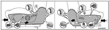
DRIVER SEAT
LHD models
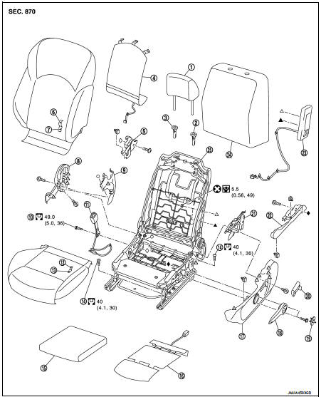
1. Headrest
2. Headrest holder (locked)
3. Headrest holder (free)
4. Seatback heater unit
5. Inner lower cover
6. Seatback trim
7. Seatback pad
8. Seat cushion inner finisher
9. Reclining device inner cover
10. Anchor bolt
11. Seat belt buckle
12. Seat cushion trim
13. Seat cushion pad
14. TORX bolt
15. Seat cushion silencer
16. Seat cushion heater unit
17. Seat cushion outer finisher
18. Lifter lever knob
19. Lifter lever knob cap
20. Reclining lever knob
21. Reclining device outer cover
22. Outer lower cover
23. Side air bag module
24. Seatback silencer
25. Seat frame & adjuster assembly
 : Pawl
 : Do not reuse
 : N·m (kg-m, in-lb)
 : N·m (kg-m, ft-lb)
PASSENGER SEAT
LHD models
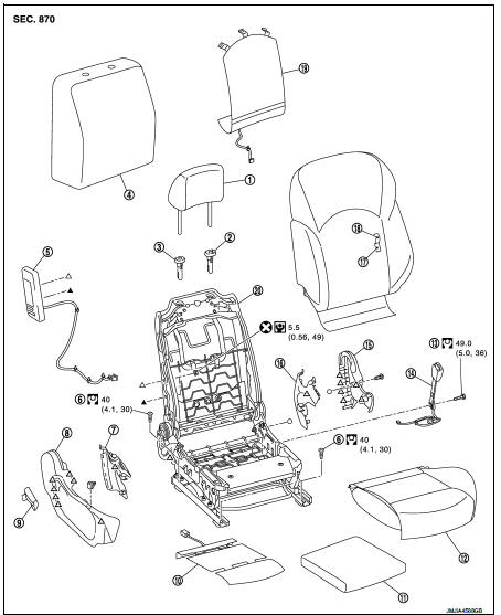
1. Headrest
2. Headrest holder (locked)
3. Headrest holder (free)
4. Seatback silencer
5. Side air bag module
6. TORX bolt
7. Reclining device outer cover
8. Seat cushion outer finisher
9. Reclining lever knob
10. Seat cushion heater unit
11. Seat cushion silencer
12. Seat cushion assembly
13. Anchor bolt
14. Seat belt buckle
15. Seat cushion inner finisher
16. Reclining device inner cover
17. Seatback pad
18. Seatback trim
19. Seatback heater unit
20. Seat frame & adjuster assembly
 : Pawl
 : Do not reuse
 : N·m (kg-m, in-lb)
 : N·m (kg-m, ft-lb)
Removal and Installation
REMOVAL
CAUTION:
Before servicing, disconnect the battery cable from negative terminal or remove
the fuse.
1. Remove headrest.
2. Set the seatback vertically.
3. Slide seat to the frontmost position.
4. Remove rear outer mounting TORX bolt.
5. Remove rear inner mounting TORX bolt.
6. Slide seat to the rearmost position.
7. Remove front outer mounting TORX bolt.
8. Remove front inner mounting TORX bolt.
9. Remove seat cushion lower harness connectors and harness fixing clamps.
CAUTION:
Before performing removal operation, check the installation position of harness
connectors and
harness fixing clamps.
10. Remove seat from the vehicle.
CAUTION:
When removing and installing, use shop cloths to protect parts from damage.
INSTALLATION
Note the following items, and install in the reverse order of removal.
CAUTION:
• When removing and installing, use shop cloths to protect parts from damage.
• When installing, tighten mounting TORX bolts according to the numerical order (1, 2, 3, and 4 as shown in the figure), starting from front inner mounting TORX bolt.
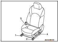
• Always fix the harness fixing clamp in position.
Seatback : Disassembly and Assembly
DISASSEMBLY
1. Remove seatback retainer installed in the lower portion of seat cushion.
2. Remove harness installed in the lower portion of seat cushion.
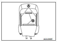
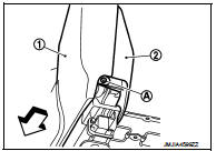
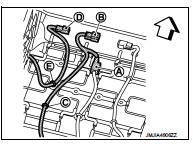
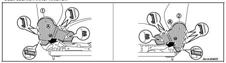
1. Disconnect seatback heater unit harness connector (A).
(with heater seat only)
2. Remove seatback heater unit harness connector fixing clip
(A) and harness fixing clamp (B). (with heater seat only)
3. Remove side air bag module harness connector fixing clip
(C) and harness fixing clamp (D).
 : Vehicle front

3. Open seatback fastener (A) and remove seatback retainer (B).
4. Remove side air bag module harness fixing clamps from seat frame & adjuster assembly.
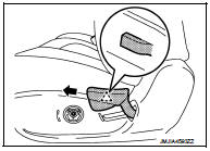
5. Use pincers, etc., to press up pawls as shown by the arrows in the figure, and remove headrest holder from seatback.
CAUTION:
Before installing headrest holder check its orientation.
(front/rear and right/left)
6. Remove side air bag module mounting nuts.
7. Remove seatback trim, seatback pad, side air bag module, and seatback heater unit (with heater seat only) from seat frame & adjuster assembly.
CAUTION:
Never subject side air bag module to impact by dropping or hitting.
8. Separate the seatback trim and seatback pad.
1. Remove side air bag module from seatback pad.
CAUTION:
For handling of side air bag module, refer to SR-22, "Removal and Installation".
2. Remove hog rings, and separate the seatback trim and seatback pad.
CAUTION:
Before performing separating operation, check the installation position of hog
rings.
9. Separate the seatback pad and seatback heater unit.
10. Remove seatback silencer from seat frame & adjuster assembly.
ASSEMBLY
Note the following, and assemble in the reverse order of disassembly.
CAUTION:
Always install the hog ring in position.
Seat cushion : Disassembly and Assembly
DISASSEMBLY
1. Remove seat cushion outer finisher.
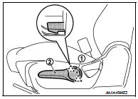
1. Disengage pawls and remove lifter lever knob cap (1).
(Driver seat only)
2. Remove fixing screws and remove lifter lever knob (2).
(Driver seat only)
 : Pawl
3. Disengage pawl using a screwdriver while pulling reclining lever knob. Slide reclining lever knob toward seat front and remove it.
 : Pawl
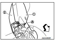
4. Tilt seat toward seat front until fixing screw (A) of seat cushion outer finisher (1) and reclining device outer cover (2) are visible. Remove fixing screw.
 : Vehicle front
5. Pull seat cushion outer finisher toward seat front. Disengage pawls and clips. Slide seat cushion outer finisher toward seat front. Remove seat cushion outer finisher.
1.
Seat cushion outer finisher
(Driver seat)
2.
Seat cushion outer finisher (Passenger seat)
 : Clip
 : Pawl
 : Metal clip
2. Remove harness installed in the lower portion of seat cushion.
Driver seat 1. Disconnect seat cushion heater unit harness connector (A).
(with heater seat only)
2. Remove seat cushion heater unit harness connector fixing
clip (B) and harness fixing clamp (C). (with heater seat only)
3. Remove seat belt buckle harness connector fixing clip (D)
and harness fixing clamp (E).
 : Vehicle front
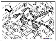
Passenger seat
1. Disconnect seat cushion heater unit harness connector (A).
(with heater seat only)
2. Remove seat cushion heater unit harness connector fixing
clip (B) and harness fixing clamp (C). (with heater seat only)
3. Disconnect occupant detection unit harness connector (D).
4. Remove seat belt buckle harness connector fixing clip (E) and harness fixing clamp (F).
 : Vehicle front
3. Remove seat cushion inner finisher.
1. Remove harness fixing clamps of seat belt buckle installed on seat frame & adjuster assembly.
2. Remove seat belt buckle mounting anchor bolt, and then remove seat belt buckle from seat frame &adjuster assembly.
3. Tilt seat toward seat front until fixing screw (A) of seat cushion inner finisher (1) and reclining device inner cover (2) are visible. Remove fixing screw.
 : Vehicle front
4. Remove fixing screws. Pull seat cushion inner finisher toward seat front. Disengage pawls. Remove seat cushion inner finisher.
1.
Seat cushion inner finisher
(Driver seat)
2.
Seat cushion inner finisher (Passenger seat)
A : Screw
 : Pawl
4. Remove seat cushion retainer from seat frame & adjuster assembly. Remove seat cushion trim, seat cushion pad, and seat cushion heater unit (with seat heater only).
5. Remove hog rings, and separate the seat cushion trim and seat cushion pad.
CAUTION:
Before performing separating operation, check the installation position of hog
rings.
6. Separate the seat cushion pad and seat cushion heater unit.
7. Remove seat cushion silencer from seat frame & adjuster assembly.
8. Remove seatback trim and seatback pad from seat frame & adjuster assembly. Refer to SE-19, "SEATBACK : Disassembly and Assembly".
9. Remove reclining device cover.
Driver seat
• Pull reclining device outer cover toward seat inner. Disengage pawls. Remove
reclining device outer
cover.
• Remove fixing screw. Pull reclining device inner cover toward seat inner. Disengage clips. Remove reclining device inner cover.
Passenger seat
• Pull reclining device outer cover toward seat inner. Disengage pawls and metal
clips. Remove reclining
device outer cover.
• Pull reclining device inner cover toward seat inner. Disengage pawls and metal clips. Remove reclining device inner cover.
10. Remove following parts from seat frame & adjuster assembly. (driver seat
only)
• Remove fixing screws. Pull outer lower cover toward seat inner and outer.
Remove clips. Remove outer
lower cover.
• Remove fixing screws. Pull inner lower cover toward seat inner. Disengage clip. Remove inner lower cover.
ASSEMBLY
Note the following, and assemble in the reverse order of disassembly.
CAUTION:
Always install the hog ring in position.

 Front seat (4WD)
Exploded View
DRIVER SEAT
LHD models
1. Headrest
2. Headrest holder (locked)
3. Headrest holder (free)
4. Seatback assembly
(with heater seat only)
5. Inner lower cover
6. Seatback trim
...
Other materials:
P1574 ASCD vehicle speed sensor
Description
The ECM receives two vehicle speed sensor signals via CAN communication line.
One is sent from combination
meter, and the other is from TCM (Transmission control module). The ECM uses
these signals for ASCD
control. Refer to EC-477, "AUTOMATIC SPEED CONTROL DEVICE (ASCD) : Sy ...
Diagnosis system (combination meter)
On Board Diagnosis Function
ON BOARD DIAGNOSIS ITEM
The combination meter allows the following diagnosis items with the on-board
diagnosis function.
METHOD OF STARTING
1. Turn ignition switch ON, and switch the trip meter to “trip A” or “trip
B”.
2. Turn ignition switch OFF.
3. While pre ...
Audio operation precautions
Radio
Place the ignition switch in the ACC or ON position and push the PWR (power/VOL
(volume)) control to turn on the radio. If you listen to the radio with the engine
not running, the ignition switch should be placed in the ACC position.
Radio reception is affected by station signal strength ...
