Nissan Juke Service and Repair Manual : Front fender
Exploded View
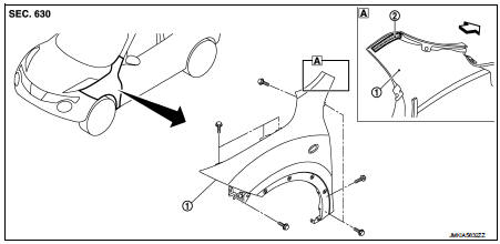
1. Front fender assembly 2. Front fender stiffener
 : Vehicle fr
Removal and Installation
REMOVAL
1. Remove front fillet molding. Refer to EXT-26, "FRONT FILLET MOLDING : Removal and Installation".
2. Remove front bumper fascia assembly. Refer to EXT-13, "Removal and Installation".
3. Remove sill cover. Refer to EXT-23, "Removal and Installation".
4. Remove fender protector. Refer to EXT-22, "Removal and Installation".
5. Remove front fender cover. Refer to EXT-20, "Exploded View".
6. Remove front combination lamp. Refer to EXL-91, "Removal and Installation".
7. Remove side turn signal lamp. Refer to EXL-98, "Removal and Installation".
8. Remove mounting bolts of front fender assembly.
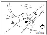
9. Remove front fender stiffener (2) from the vehicle body while carefully pulling upper portion of front fender (1) toward vehicle outside.
 : Vehicle front
10. Remove front fender assembly.
CAUTION
:
An viscous urethane foam is installed on the back surface of front fender.
When removing the
front fender, be careful to not deform the front fender while performing the
procedure and removing
the viscous urethane foam a little at a time.
INSTALLATION
Note the following items, and install in the reverse order of removal.
CAUTION:
• After installation, apply the touch-up paint (the body color) onto the head of
front fender mounting
bolts.
• After installation, adjust the following part.
- Hood assembly: Refer to DLK-305, "HOOD ASSEMBLY : Adjustment".
- Front door: Refer to DLK-319, "DOOR ASSEMBLY : Adjustment".
 Radiator core support
HR16DE
HR16DE : Exploded View
1. Radiator core support upper
2. Air guide RH (MT models)
3. Radiator core support lower
4. Air guide LH 5. Air guide (upper)
6. Air guide LH (CVT models)
7. ...
 Front door
Exploded View
1. Front door panel
2. Grommet
3. TORX bolt
4. Door striker
5. Door pad
6. Bumper rubber
7. Door check link
8. Door hinge (lower)
9. Door hinge (upper)
10. Grommet
: D ...
Other materials:
U1001 Can comm circuit
Description
CAN (Controller Area Network) is a serial communication line for real time
application. It is an on-vehicle multiplex
communication line with high data communication speed and excellent error
detection ability. Many electronic
control units are equipped onto a vehicle, and each c ...
Basic inspection
DIAGNOSIS AND REPAIR WORK FLOW
Work Flow
OVERALL SEQUENCE
DETAILED FLOW
1.INTERVIEW THE CUSTOMER FOR THE SYMPTOM
Interview the customer for the symptom (the condition and the environment
when the incident/malfunction
occurs).
>> GO TO 2.
2.CHECK SYMPTOM
Check the symptom from ...
B210C starter control relay
DTC Logic
DTC DETECTION LOGIC
NOTE:
• If DTC B210C is displayed with DTC U1000, first perform the trouble diagnosis
for DTC U1000. Refer to
PCS-30, "DTC Logic".
• When IPDM E/R power supply voltage is low (Approx. 7 - 8 V for about 1
second), the DTC B210C may be
detected.
DTC ...
