Nissan Juke Service and Repair Manual : Front drive shaft boot
Exploded View
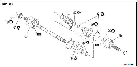
1. Circular clip
2. Dust shield
3. Housing assembly
4. Boot band
5. Boot
6. Damper band
7. Dynamic damper
8. Circular clip
9. Joint sub-assembly
 : Wheel side
 : Fill NISSAN Genuine grease or
equivalent.
 : Always replace after every
disassembly.
RIGHT SIDE
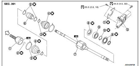
1. Joint sub-assembly
2. Circular clip
3. Boot band
4. Boot
5. Damper band
6. Dynamic damper
7. Housing assembly
8. Dust shield
9. Support bearing
10. Snap ring
11. Plate
12. Support bearing bracket
: Wheel side
 : Fill NISSAN Genuine grease or
equivalent.
 : Always replace after every
disassembly.
 : N·m (kg-m, ft-lb)
Wheel side : Removal and Installation
REMOVAL
1. Remove tires. Refer to WT-7, "Removal and Installation".
2. Remove wheel sensor and sensor harness. Refer to BRC-84, "FRONT WHEEL SENSOR : Exploded View" (Without ESP) or BRC-224, "FRONT WHEEL SENSOR : Exploded View" (With ESP).
3. Remove lock plate from strut assembly. Refer to FSU-10, "Removal and Installation".
4. Remove caliper assembly. Hang caliper assembly not to interfere with work. Refer to BR-57, "BRAKE CALIPER ASSEMBLY : Removal and Installation" (LHD) or BR-123, "BRAKE CALIPER ASSEMBLY : Removal and Installation" (RHD).
CAUTION:
Never depress brake pedal while brake caliper is removed.
5. Remove disc rotor. Refer to FAX-68, "Removal and Installation".
6. Remove cotter pin, and then loosen wheel hub lock nut. Refer to FAX-68, "Removal and Installation".
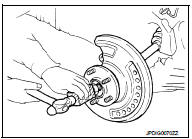
7. Patch wheel hub lock nut with a piece of wood. Hammer the wood to disengage wheel hub assembly from drive shaft.
NOTE
:
Use suitable puller, if wheel hub assembly and drive shaft cannot
be separated even after performing the above procedure.
8. Remove wheel hub lock nut. Refer to FAX-68, "Removal and Installation".
9. Remove strut assembly from steering knuckle. Refer to FSU-10, "Removal and Installation".
10. Remove drive shaft from wheel hub assembly.
CAUTION:
• Never place drive shaft joint at an extreme angle. Also be
careful not to overextend slide joint.
• Never allow drive shaft to hang down without support for joint sub-assembly, shaft and the other parts.
11. Remove boot bands, and then remove boot from joint sub-assembly.
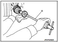
12. Screw drive shaft puller (A) (commercial service tool) into joint sub-assembly screw part to a length of 30 mm (1.18 in) or more.
Support drive shaft with one hand and pull out joint sub-assembly from shaft.
CAUTION:
• Align drive shaft puller and drive shaft and remove them
by pulling firmly and uniformly.
• If joint sub-assembly cannot be pulled out, try after removing drive shaft from vehicle. Refer to FAX-81, "WHEEL SIDE : Disassembly and Assembly".
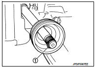
13. Remove circular clip (1) from shaft.
14. Remove boot from shaft.
INSTALLATION
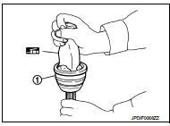
1. Clean the old grease on joint sub-assembly with paper waste.
2. Fill serration slot joint sub-assembly (1) with NISSAN genuine grease or equivalent until the serration slot and ball groove become full to the brim.
CAUTION:
After applying grease, use a paper waste to wipe off old
grease that has oozed out.
3. Install boot and boot bands to shaft.
CAUTION:
• Wrap serration on shaft with tape to protect the boot from
damage.
• Never reuse boot and boot band.
4. Remove the tape wrapped around the serration on shaft.
5. Position the circular clip (1) on groove at the shaft edge.
CAUTION:
Never reuse circular clip.
NOTE:
Drive joint inserter is recommended when installing circular clip.
6. Align both center axles of the shaft edge and joint sub-assembly.
Then assemble shaft with joint sub-assembly holding circular clip.
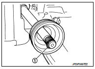
7. Install joint sub-assembly (1) to shaft using plastic hammer.
CAUTION:
• Check circular clip is properly positioned on groove of the
joint sub-assembly.
• Confirm that joint sub-assembly is correctly engaged while rotating drive shaft.
8. Apply the specified amount of grease into the boot inside from large diameter side of boot.
Grease amount : Refer to FAX-90, "Drive Shaft".
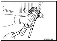
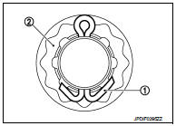
9. Install the boot securely into grooves (indicated by “*” marks) shown in the figure.
CAUTION:
If grease adheres to the boot mounting surface (indicated
by “*” marks) on the shaft or joint sub-assembly, boot may
be removed. Remove all grease from the boot mounting
surface.
10. To prevent the deformation of the boot, adjust the boot installation length (L) to the specified value shown below by inserting the suitable tool into inside of the boot from the large diameter side of the boot and discharging the inside air.
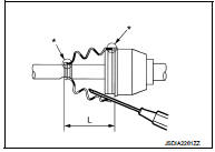
L : Refer to FAX-90, "Drive Shaft".
CAUTION:
• If the boot installation length exceeds the standard, it may cause breakage of
the boot.
• Be careful not to touch the inside of the boot with a tip of tool.
11. Secure the large and small ends of the boot with boot bands using the boot band crimping tool (A) (SST: KV40107300).
CAUTION:
• Never reuse boot band.
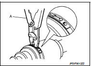
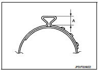
• Secure boot band so that dimension (A) meets the specification as shown in the figure.
A : 5.0 mm (0.197 in) or less.
12. Check that displacement does not occur when boot is rotated with the joint sub-assembly and shaft fixed.
CAUTION:
• Reinstall them using boot bands when boot installation positions become
incorrect.
• Never reuse boot band.
13. Clean the matching surface of wheel hub lock nut and wheel hub assembly.
CAUTION:
Never apply lubricating oil to these matching surface.
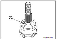
14. Clean the matching surface of drive shaft, wheel hub assembly.
And then apply paste [service parts (440037S000)] to surface (A) of joint sub-assembly of drive shaft.
CAUTION:
Apply paste to cover entire flat surface of joint sub-assembly
of drive shaft.
15. Insert drive shaft to wheel hub assembly, and then temporarily tighten wheel hub lock nut.
CAUTION
:
Be sure to use torque wrench to tighten the wheel hub lock nut. Never use a
power tool.
16. Install strut assembly to steering knuckle. Refer to FSU-10, "Removal and Installation".
17. Install disc rotor. Refer to FAX-68, "Removal and Installation".
18. Install caliper assembly to steering knuckle. Refer to BR-57, "BRAKE CALIPER ASSEMBLY : Removal and Installation" (LHD) or BR-123, "BRAKE CALIPER ASSEMBLY : Removal and Installation" (RHD).
19. Install lock plate to strut assembly. Refer to FSU-10, "Removal and Installation".
20. Install wheel sensor and sensor harness. Refer to BRC-84, "FRONT WHEEL SENSOR : Exploded View" (Without ESP) or BRC-224, "FRONT WHEEL SENSOR : Exploded View" (With ESP).
21. Use the following torque range for tightening the wheel hub lock nut.
 : 180 – 185 N·m (18.4 – 18.8
kg-m, 133 – 136 ft-lb)
CAUTION:
• Since the drive shaft is assembled by press-fitting, use the tightening torque
range for the wheel
hub lock nut.
• Be sure to use torque wrench to tighten the wheel hub lock nut. Never use a power tool.
• Never reuse wheel hub lock nut.
NOTE:
Wheel hub lock nut tightening torque does not over torque for avoiding axle noise, and does not less than torque for avoiding looseness.
22. When installing a cotter pin (1) and adjusting cap (2), securely bend the basal portion to prevent rattles.
CAUTION:
Never reuse cotter pin.
23. Install tires. Refer to WT-7, "Removal and Installation".
24. Perform inspection after installation. Refer to FAX-76, "Inspection".
Transaxle side : Removal and Installation
Remove boot after drive shaft is removed from the vehicle.
• For drive shaft removal and installation, refer to FAX-78, "LEFT SIDE : Removal and Installation" (LEFT SIDE) or FAX-79, "RIGHT SIDE : Removal and Installation" (RIGHT SIDE).
• For drive shaft disassembly and assembly, refer to FAX-84, "TRANSAXLE SIDE : Disassembly and Assembly".
Inspection
INSPECTION AFTER INSTALLATION
1. Check wheel sensor harness for proper connection. Refer to BRC-84, "FRONT WHEEL SENSOR : Exploded View" (Without ESP) or BRC-224, "FRONT WHEEL SENSOR : Exploded View" (With ESP).
2. Check the wheel alignment. Refer to FSU-7, "Inspection".
 Front wheel hub and K
Exploded View
1. Steering knuckle
2. Splash guard
3. Hub bolt
4. Wheel hub assembly (Bearing-integrated
type)
5. Disc rotor
6. Wheel hub lock nut
7. Adjusting cap
8. Cotter pin
A. Tigh ...
 Front drive shaft
Exploded View
LEFT SIDE
1. Circular clip
2. Dust shield
3. Housing assembly
4. Boot band
5. Boot
6. Damper band
7. Dynamic damper
8. Circular clip
9. Joint sub-assembly
: Wheel side ...
Other materials:
Diagnosis system (ECM)
Diagnosis description
Diagnosis description : 1st Trip Detection
Logic and Two Trip Detection Logic
When a malfunction is detected for the first time, 1st trip DTC and 1st trip
Freeze Frame data are stored in the
ECM memory. The MIL will not illuminate at this stage. <1st trip>
If the s ...
B2622 inside antenna
DTC Logic
DTC DETECTION LOGIC
DTC CONFIRMATION PROCEDURE
1.PERFORM DTC CONFIRMATION PROCEDURE
1. Select “INTELLIGENT KEY” of “BCM” using CONSULT-III.
2. Select “INSIDE ANT DIAGNOSIS” in “WORK SUPPORT” mode.
3. Perform inside key antenna (“INSIDE ANT DIAGNOSIS”) on “WORK SUPPORT” of
“INTELL ...
Front disc brake
Brake pad : Inspection and Adjustment
INSPECTION
Check brake pad wear thickness from an inspection hole on cylinder
body. Check using a scale if necessary.
Wear thickness : Refer to BR-71, "Front Disc Brake".
ADJUSTMENT
Burnish contact surfaces between disc rotor and brake pads acc ...
