Nissan Juke Service and Repair Manual : Front door lock
Exploded View
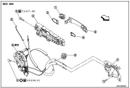
1. Door key cylinder assembly (driver
side)
Outside handle escutcheon (passenger
side)
2. Rear gasket
3. Outside handle bracket
4. TORX bolt
5. Key rod (driver side)
6. Door lock assembly
7. Inside handle
8. Outside handle
9. Front gasket
10. Cable clip
 : Pawl
 : Vehicle front
 : Do not reuse
 : N·m (kg-m, in-lb)
 : Body grease
Door lock
DOOR LOCK : Removal and Installation
REMOVAL
1. Remove front door glass and front door lower sash (rear). Refer to GW-17, "Removal and Installation".
2. Remove inside handle. Refer to DLK-339, "INSIDE HANDLE : Removal and Installation".
3. Disengage inside handle cable and lock knob cable from cable clip.
4. Remove outside handle bracket. Refer to DLK-339, "OUTSIDE HANDLE : Removal and Installation".
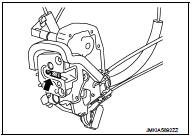
5. Remove door lock assembly TORX bolts.
6. Disconnect door lock actuator connector, and then remove door lock assembly.
INSTALLATION
Note the following items, and install in the reverse order of removal.
CAUTION:
• Never reuse TORX bolt. Always replace it with a new one when it is removed.
• Check door open/close, lock/unlock operation after installation.
• Check door lock cable is properly engaged with outside handle bracket.
• Check door lock assembly for poor lubrication. Apply body grease to door lock if necessary.
 : Grease up point
Inside handle
INSIDE HANDLE : Removal and Installation
REMOVAL
1. Remove front door finisher. Refer to INT-13, "Removal and Installation".
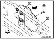
2. Remove inside handle mounting bolt (A).
3. Disengage inside handle (1) from door panel (2) while sliding inside handle toward vehicle rear, and then separate inside handle.
 : Vehicle front
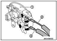
4. Disengage inside handle cable (3) and lock knob cable (2), and then remove inside handle (1).
INSTALLATION
Note the following item, and install in the reverse order of removal.
CAUTION:
Check door open/close, lock/unlock operation after inst
allation.
Outside handle
OUTSIDE HANDLE : Removal and In
REMOVAL
1. Fully close the front door glass.
2. Remove front door finisher. Refer to INT-13, "Removal and Installation".
3. Remove sealing screen.
NOTE
:
Cut the butyl-tape so that some parts of the butyl-tape do not remain on the
sealing screen, if the sealing
screen is reused.
4. Disengage lock holder (1), and then separate key rod (3) from door lock assembly (2).(Driver side)
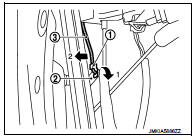
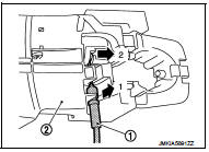
5. Disconnect harness connector of door antenna (1) and door request switch (2) and remove harness clamp (3).
 : Vehicle front
6. Remove grommet (1) of door side. Loosen, through grommet hole, TORX bolt (2) that fixes door lock cylinder. (For passenger side, TORX bolt fixes outside handle escutcheon.)
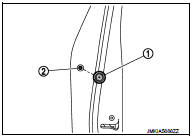
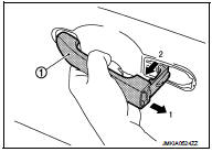
7. While pulling outside handle, remove door key cylinder assembly (diver side) or outside handle escutcheon (passenger side).
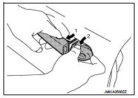
8. While pulling outside handle (1), slide toward rear of vehicle to remove outside handle.
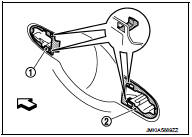
9. Remove front gasket (1) and rear gasket (2).
 : Vehicle front
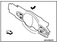
10. Slide outside handle bracket toward rear of vehicle to remove.
 : Vehicle front
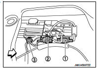
11. Disconnect outside handle cable (1) from outside handle bracket (2).
INSTALLATION
Note the following items, and install in the reverse order of removal.
CAUTION:
• When installing key rod, rotate key rod holder until a click is felt.
• Check that door lock cables are normally engaged with inside handle and outside handle.
• After installation, check door open/close, and lock/unlock operation.
 Hood lock
Exploded View
1. Hood lock control cable assembly
2. Hood lock assembly
: Clip
: N·m (kg-m, ft-lb)
: Body grease
Hood lock
HOOD LOCK : Removal and Installation
REMOVAL
1. Remove front cent ...
 Rear door lock
Exploded View
1. Outside handle assembly
2. Rear door sealing screen
3. Door lock assembly
4. TORX bolt
5. Inside handle
: Clip
: Pawl
: Vehicle front
: Do not reuse
: N·m (kg-m, in-lb) ...
Other materials:
Front fender
Exploded View
1. Front fender assembly
2. Front fender stiffener
: Vehicle fr
Removal and Installation
REMOVAL
1. Remove front fillet molding. Refer to EXT-26, "FRONT FILLET MOLDING :
Removal and Installation".
2. Remove front bumper fascia assembly. Refer to EXT-13, "Remo ...
Fuel filter
Exploded View
Removal and Installation
REMOVAL (RHD)
1. Remove quick connectors in the following procedures.
• Pinch quick connector square-parts with your fingers, and pull
out the quick connector by hand.
• If quick connector and tube on vehicle are stuck, push and pull
several times ...
Precaution Necessary for Steering Wheel Rotation after Battery Disconnect
NOTE:
• Before removing and installing any control units, first turn the ignition
switch to the LOCK position, then disconnect
both battery cables.
• After finishing work, confirm that all control unit connectors are connected
properly, then re-connect both
battery cables.
• Always use CONS ...
