Nissan Juke Service and Repair Manual : Front disc brake
Brake pad : Inspection and Adjustment
INSPECTION
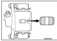
Check brake pad wear thickness from an inspection hole on cylinder body. Check using a scale if necessary.Wear thickness : Refer to BR-137, "Front Disc Brake".
ADJUSTMENT
Burnish contact surfaces between disc rotor and brake pads according to the following procedure after refinishing or replacing brake pads, or if a soft pedal occurs at very low mileage.
CAUTION:
• Be careful of vehicle speed because the brake does not operate firmly/securely
until pads and disc
rotor are securely fitted.
• Only perform this procedure under safe road and traffic conditions. Use extreme caution
.
1. Drive vehicle on straight, flat road.
2. Depress brake pedal with the power to stop vehicle within 3 to 5 seconds until the vehicle stops.
3. Drive without depressing brake for a few minutes to cool the brake.
4. Repeat steps 1 to 3 until pad and disc rotor are securely fitted.
Disc rotor : Inspection and Adjustment
INSPECTION
Appearance
Check surface of disc rotor for uneven wear, cracks, and serious damage. Replace
it if necessary.
• MR16DDT: Refer to FAX-11, "Removal and Installation".
• HR16DE: Refer to FAX-43, "Removal and Installation".
• K9K: Refer to FAX-68, "Removal and Installation".
Runout
1. Fix the disc rotor to the wheel hub and bearing assembly with
wheel nuts (2 points at least).
2. Check the wheel bearing axial end play before the inspection.
• MR16DDT: Refer to FAX-9, "Inspection".
• HR16DE: Refer to FAX-41, "Inspection".
• K9K: Refer to FAX-66, "Inspection".
3. Inspect the runout with a dial indicator to measure at 10 mm (0.39 in) inside the disc edge.
Runout (with it attached to the vehicle) : Refer to BR-137, "Front Disc Brake".
4. Find the installation position that has a minimum runout by shifting the disc rotor-to-wheel hub and bearing assembly installation position by one hole at a time if the runout exceeds the limit value.
• Refinish the disc rotor if the runout is outside the limit even after performing the above operation.
CAUTION
:
• Check in advance that the thickness of the disc rotor is wear thickness + 0.3
mm (0.012 in) or more.
• If the thickness is less than wear thickness + 0.3 mm (0.012 in), replace the disc rotor.
- MR16DDT: Refer to FAX-11, "Removal and Installation".
- HR16DE: Refer to FAX-43, "Removal and Installation".
- K9K: Refer to FAX-68, "Removal and Installation".
Wear thickness : Refer to BR-137, "Front Disc Brake".
Thickness
Check the thickness of the disc rotor using a micrometer. Replace
the disc rotor if the thickness is below the wear limit.
• MR16DDT: Refer to FAX-11, "Removal and Installation".
• HR16DE: Refer to FAX-43, "Removal and Installation".
• K9K: Refer to FAX-68, "Removal and Installation".
Wear thickness : Refer to BR-137, "Front Disc Brake".
ADJUSTMENT
Burnish contact surfaces between disc rotors and brake pads according to the following procedure after refinishing or replacing disc rotor, or if a soft pedal occurs at very low mileage.
CAUTION:
• Be careful of vehicle speed because the brake does not operate firmly/securely
until pad and disc
rotor are securely fitted.
• Only perform this procedure under safe road and traffic conditions. Use extreme caution.
1. Drive vehicle on straight, flat road.
2. Depress brake pedal with the power to stop vehicle within 3 to 5 seconds until the vehicle stops.
3. Drive without depressing brake for a few minutes to cool the brake.
4. Repeat steps 1 to 3 until pad and disc rotor are securely fitted.
 Brake booster
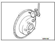
Inspection
OPERATION
Depress the brake pedal several times at 5-second intervals with the engine
stopped. Start the engine with the
brake pedal fully depressed. Check that the clearance between b ...
 Rear disc brake
Brake pad : Inspection and Adj
INSPECTION
Check brake pad wear thickness from an inspection hole on cylinder
body. Check using a scale if necessary.
Wear thickness : Refer to BR-137, "Rear Di ...
Other materials:
Liquid Gasket
REMOVAL OF LIQUID GASKET SEALING
• After removing mounting nuts and bolts, separate the mating surface
using the seal cutter [SST: KV10111100] (A) and remove old
liquid gasket sealing.
CAUTION:
Be careful not to damage the mating surfaces.
• Tap the seal cutter [SST: KV10111100] to insert it ...
Engine bucking
Description
CHART 9: ENGINE BUCKING
Diagnosis Procedure
1.CHECK ECM POWER SUPPLY AND GROUND CIRCUIT
Check ECM power supply and ground circuit. Refer to EC-885, "Diagnosis
Procedure".
Is the inspection result normal?
YES >> GO TO 2.
NO >> Repair or replace harness o ...
LAN System can system (type 5)
DTC/CIRCUIT DIAGNOSIS
Main line between IPDM-E and DLC circuit
Diagnosis Procedure
1.CHECK CONNECTOR
1. Turn the ignition switch OFF.
2. Disconnect the battery cable from the negative terminal.
3. Check the following terminals and connectors for damage, bend and loose
connection (connector s ...
