Nissan Juke Service and Repair Manual : Front bumper
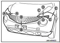
Exploded View
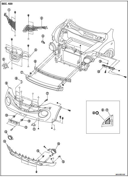
1. Front side grille RH
2. Front side grille LH
3. Bumper side bracket RH
4. Front center grille
5. Emblem
6. Bumper reinforcement
7. Energy absorber
8. Bumper end rubber RH
9. Bumper fascia
10. Screw grommet
11. Bumper bracket cover
12. License plate bracket
13. Front fog bracket RH
14. Bumper fascia lower
15. U nut
16. Front fog bracket LH
17. Bumper end rubber LH
18. Bumper side bracket LH
19. Screw grommet
20. double-sided tape
[t: 1.2 mm (0.047 in)]
 : Pawl
 : Do not reuse
Removal and Installation
CAUTION:
Bumper fascia is made of resin. Never apply strong force to it, and be careful
to prevent contact with
oil.
REMOVAL
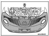
1. Fully open hood assembly.
2. Remove clips (A) of bumper upper side.
3. Remove front fillet molding front side. Refer toEXT-26, "FRONT FILLET MOLDING : Removal and Installation".
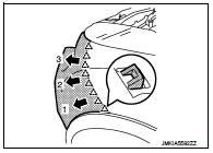
4. Remove bumper fascia assembly fixing screws (A) (LH and RH).
5. Remove air guide fixing screws, and then remove air guide (LH and RH).Refer to EXT-22, "Exploded View".
6. Remove clips of bumper lower side.
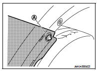
7. Pull bumper fascia side toward the vehicle side to disengage the fitting of bumper side bracket and bumper fascia side as shown by the arrow in the figure.
 : Pawl
8. CAUTION:
When removing bumper fascia assembly, 2 workers are
required so as to prevent it from dropping.
9. Disconnect front fog lamp harness connectors. (with fog lamp) 10. Remove bumper fascia assembly.
11. Remove the following parts after removing bumper fascia assembly.
• Front fog lamp assembly (LH and RH). (with fog lamp)
• Front fog lamp finishers (LH and RH). (with out fog lamp)
• Bumper fascia lower
• License plate bracket
12. Remove bumper energy absorber.
13. Remove bumper reinforcement mounting nuts, and then remove bumper reinforcement.
14. Remove bumper side bracket mounting screws, and then remove bumper side bracket.
INSTALLATION
Note the following items, and then install in the reverse order of removal.
NOTE
:
• The following table shows the specified values for checking normal
installation status.
• Fitting adjustment cannot be performed.

 Rear bumper
Exploded View
1. Bumper side bracket LH
2. Bumper closing LH
3. Bumper fascia assembly
4. Reflex reflector LH
5. Rear panel lower
6. U nut
7. Bumper fascia lower
8. Reflex reflector RH ...
Other materials:
Power supply and ground circuit
Diagnosis Procedure
1.CHECK FUSES AND FUSIBLE LINK
Check that the following IPDM E/R fuses or fusible links are not blown.
Is the fuse fusing?
YES >> Replace the blown fuse or fusible link after repairing the affected
circuit if a fuse or fusible link is
blown.
NO >> GO TO 2. ...
Evaporative emission system
Inspection
1. Visually inspect EVAP vapor lines for improper attachment and for cracks,
damage, loose connections,
chafing and deterioration.
2. Check EVAP canister as follows:
a. Block port (B). Orally blow air through port (A).
Check that air flows freely through port (C).
b. Block port (A ...
Changing engine oil and filter
Change the engine oil and filter according to the maintenance log shown in the
NISSAN Service and Maintenance Guide.
Vehicle set-up
1. Park the vehicle on a level surface and apply the parking brake.
2. Run the engine until it reaches the operating temperature.
3. Turn the engine off and wait ...
