Nissan Juke Service and Repair Manual : Exhaust manifold
Exploded View
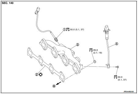
1. Exhaust gas temperature sensor 1
2. Gasket
3. Exhaust manifold
4. Exhaust gas pressure sensor 1
A. To cylinder head
 : N·m (kg-m, ft-lb)
 : Always replace after every
disassembly.
Removal and Installation
REMOVAL
1. Remove turbocharger assembly. Refer to EM-284, "Exploded View".
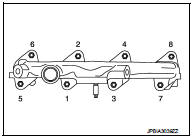
2. Loosen exhaust manifold mounting nuts in the reverse order as shown.
3. Remove exhaust manifold.
INSTALLATION
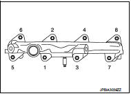
1. Tighten the mounting nuts in numerical order as shown.
2. Install in reverse order of removal after this step.
Inspection
Start engine and raise engine speed to check no exhaust emission leaks.
 Turbocharger
Exploded View
1. Exhaust manifold
2. Turbocharger
3. Gasket
4. Turbocharger outlet duct
5. Oil outlet hose
6. Clamp
7. Oil return pipe
8. Gasket
9. Washer
10. Oil supply tube
11. O ...
 Oil pan
Exploded View
1. Baffle plate
2. Gasket
3. Oil pan
4. O-ring
5. Drain plug
6. Oil level gauge guide
7. Transaxle
8. Crankshaft position sensor (POS)
: N·m (kg-m, ft-lb)
: N·m (kg-m, i ...
Other materials:
B2615 blower relay circuit
DTC Logic
DTC DETECTION LOGIC
DTC CONFIRMATION PROCEDURE
1.PERFORM DTC CONFIRMATION PROCEDURE
1. Turn ignition switch ON under the following conditions, and wait for 1
second or more.
CVT models
- Selector lever is in the P or N position
- Do not depress brake pedal
M/T models
- Do no ...
Electric ignition system
Electric ignition system : System Diagram
Electric ignition system : System Description
INPUT/OUTPUT SIGNAL CHART
*1: CVT models
*2: M/T models
*3: ECM determines the start signal status by the signals of engine speed and
battery voltage.
SYSTEM DESCRIPTION
Firing order: 1 ...
P1642 thermoplunger control unit
DTC Logic
DTC DETECTION LOGIC
Diagnosis Procedure
1.CHECK THERMOPLUNGER CONTROL UNIT POWER SUPPLY CIRCUIT
1. Turn ignition switch OFF.
2. Disconnect thermoplunger control unit harness connector.
3. Check the voltage between thermoplunger control unit harness connector and
ground.
Is the ...
