Nissan Juke Service and Repair Manual : Exhaust manifold
Exploded View
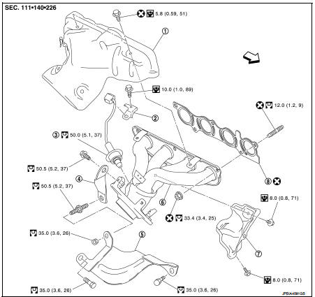
1. Exhaust manifold cover
2. Harness bracket
3. Air fuel ratio sensor 1
4. Exhaust manifold stay
5. Heat insulator
6. Exhaust manifold
7. Exhaust manifold cover
8. Gasket
 : Engine front
 : Always replace after every
disassembly.
 : N·m (kg-m, in-lb)
 : N·m (kg-m, ft-lb)
Removal and Installation
REMOVAL
1. Remove exhaust front tube. Refer to EX-12, "Exploded View".
2. Remove air duct. Refer to EM-161, "Exploded View".
3. Remove the harness bracket fixing the harness connector of the air-fuel ratio sensor from the cylinder head on the rear right side.
4. Remove exhaust manifold cover.
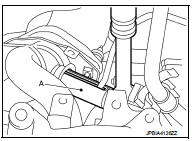
5. Remove the air fuel ratio sensor 1.
• Using heated oxygen sensor wrench [SST: KV10117100] (A), remove air fuel ratio sensor 1.
CAUTION:
• If O2 sensor is dropped on to a hard surface like a concrete
floor from a height of 0.5 m or more, discard the
sensor and use a new one.
• Clean the mounting area of O2 sensor before installing a new O2 sensor.
NOTE:
The exhaust manifold can be removed and installed without removing the air fuel ratio sensor 1 (Disassembly of harness connector is necessary).
6. Remove exhaust manifold side mounting bolt of exhaust manifold stay.
7. Remove the harness bracket of air fuel ratio sensor 1 from cylinder head.
8. Remove exhaust manifold.
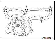
• Loosen nuts in reverse order as shown in the figure.
9. Remove stud bolt from cylinder head.
• Using TORX socket.
10. Remove exhaust manifold cover from exhaust manifold back side.
INSTALLATION
NOte the following, and install in the reverse order of removal.
Exhaust manifold
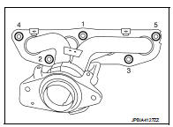
1. Tighten nuts in numerical order as shown in the figure.
2. Tighten to the specified torque again.
Inspection
INSPECTION AFTER REMOVAL
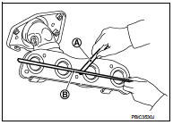
Surface Distortion
• Using feeler gauge (A) and straightedge (B), check the surface distortion of exhaust manifold mating surface in each exhaust port and entire part.
Limit : Refer to EM-251, "Exhaust Manifold".
• If it exceeds the limit, replace exhaust manifold.
 Intake manifold
Exploded View
1. EVAP canister purge volume control
solenoid valve
2. Hose clamp
3. Vacuum hose
4. Intake manifold support
5. Gasket
6. Intake manifold
7. Electric throttle control actua ...
 Oil pan (lower)
Exploded View
With Oil Cooler
1. Rear oil seal
2. O-ring
3. Oil pan (upper)
4. Oil pump chain tensioner (for oil
pump drive chain)
5. Oil pump drive chain
6. Crankshaft sprocket
7. Oil ...
Other materials:
B1084 seat belt Pre-tensioner RH
DTC Logic
DTC DETECTION LOGIC
DTC CONFIRMATION PROCEDURE
1.CHECK SELF-DIAG RESULT
With CONSULT-III
1. Turn ignition switch ON.
2. Perform “Self Diagnostic Result” mode of “AIR BAG” using CONSULT-III.
Without CONSULT-III
1. Turn ignition switch ON.
2. Check the air bag warning lamp statu ...
Back door trim
Exploded View
1. Back door side finisher RH
2. Rear parcel shelf finisher
3. Back door side finisher LH
4. Back door lower finisher
5. Emergency lid
6. Back door pull handle
: Clip
: Pawl
Back door pull handle : Removal and Installation
REMOVAL
CAUTION:
• When removing, always use ...
P0137 HO2S2
DTC Logic
DTC DETECTION LOGIC
The heated oxygen sensor 2 has a much longer switching time
between rich and lean than the air fuel ratio (A/F) sensor 1. The oxygen
storage capacity of the three way catalyst 1 causes the longer
switching time. To judge the malfunctions of heated oxygen sensor
2, ...
